3
PANEL DESCRIPTION
2
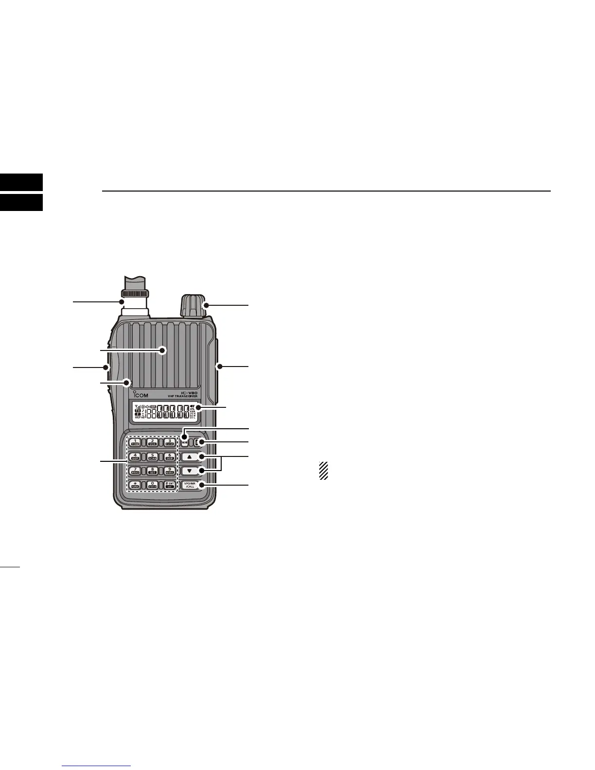
■ Front, top and side panels
q PTT SWITCH [PTT]
➥ Push and hold to transmit, release to receive. (p. 17)
For IC-V80E only
➥ Push briefly, then push and hold to transmit a 1750 Hz
tone burst signal. (p. 22)
w ANTENNA CONNECTOR
Connect the antenna here. (p. 1)
e CONTROL DIAL [VOL]
➥ Adjust the volume level. (p. 14)
➥ During the Set mode, or Initial Set mode, rotate to se-
lect a desired option or value. (pp. 38, 43)
r EXTERNAL SPEAKER/MICROPHONE JACKS [SP MIC]
Used to connect an optional speaker-microphone, plug
adapter cable or cloning cable. The internal microphone
and speaker will not function when an option is con-
nected. See page 51 for a list of available options.
Be sure to turn power OFF before connecting/discon-
necting optional equipment to/from the [SP/MIC] jack.
t MONITOR KEY [MONI]
➥ Push and hold to open the squelch temporarily to mon-
itor the operating frequency. (p. 14)
➥ While pushing and holding this key, push [] or [] to
adjust the squelch level. (p. 14)
➥ Enters or sends the DTMF code ‘A.’ (pp. 35, 36)