6
2
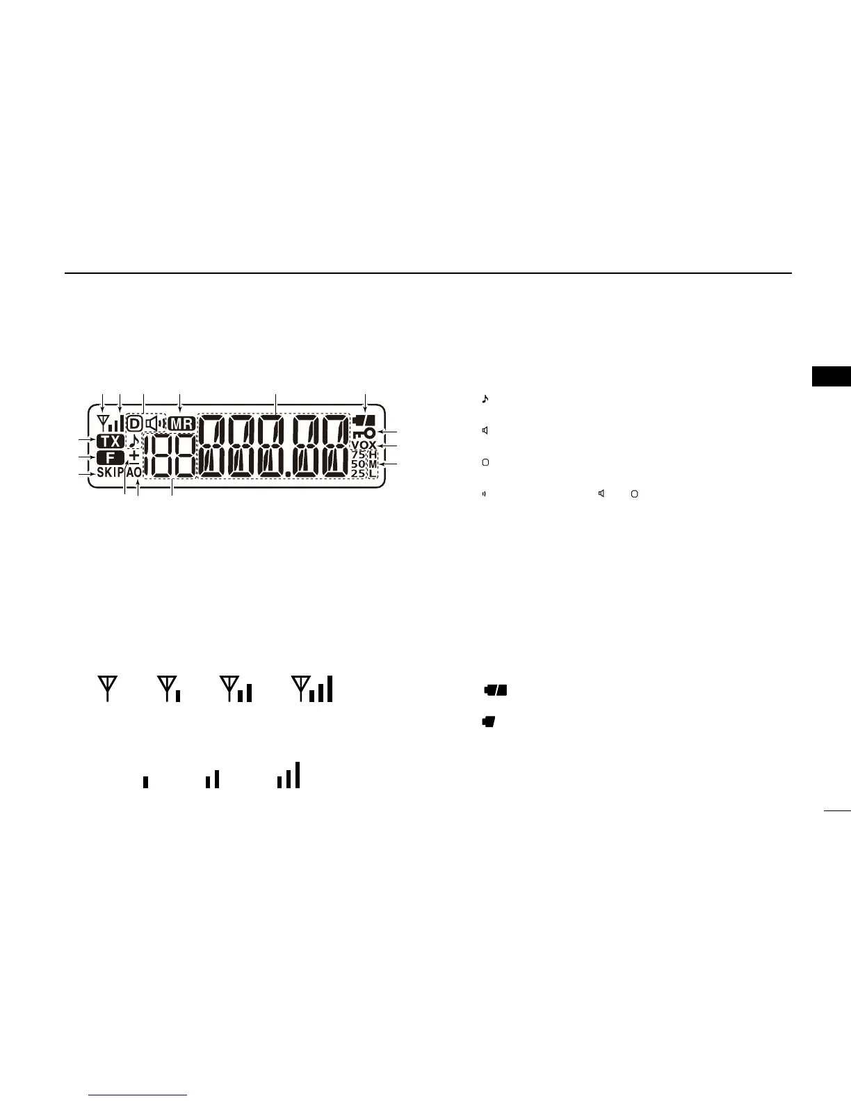
■ Function display
q BUSY INDICATOR
➥ Appears when a signal is being received, or the
squelch is open.
➥ Blinks while the monitor function is ON. (p. 14)
w SIGNAL INDICATOR
➥ Shows the strength of the received signal. (p. 17)
➥ While transmitting, shows the output power level.
(p. 17)
e TONE INDICATOR
➥ “ ” appears while the repeater tone encoder is ON.
(p. 20)
➥ “ ” appears while the tone squelch function is ON.
(p. 33)
➥ “
” indicator while the pocket
beep function (with CTCSS or DTCS) is ON. (p. 33)
r MEMORY INDICATOR
Appears when the memory mode is selected. (pp. 15, 24)
t FREQUENCY READOUT
➥ Displays the operating frequency, memory channel,
Set modes contents and a variety of other information.
• The decimal point blinks during scan.
➥ During memory mode operation, the programmed
memory name is displayed.
y BATTERY INDICATOR (p. 13)
➥ “ ” (battery indicators) appear when the battery
pack/case is attached.
➥ “ ” appears when the battery pack must be changed,
or batteries must be replaced.
2
PANEL DESCRIPTION