ClearMark™ Installation, Operation & User Manual – Page 19
V 1.S.10 January 2021
Inputs and Outputs I/O
The printer has several inputs and outputs. Their type and location are listed below:
Inputs
All inputs are 24 VDC PNP:
Internal photocell 1 – Sensor above the printer head
Internal photocell 2 – Sensor above the printer head
Button 1 on the print head
Button 2 on the print head
Button 3 on the print head
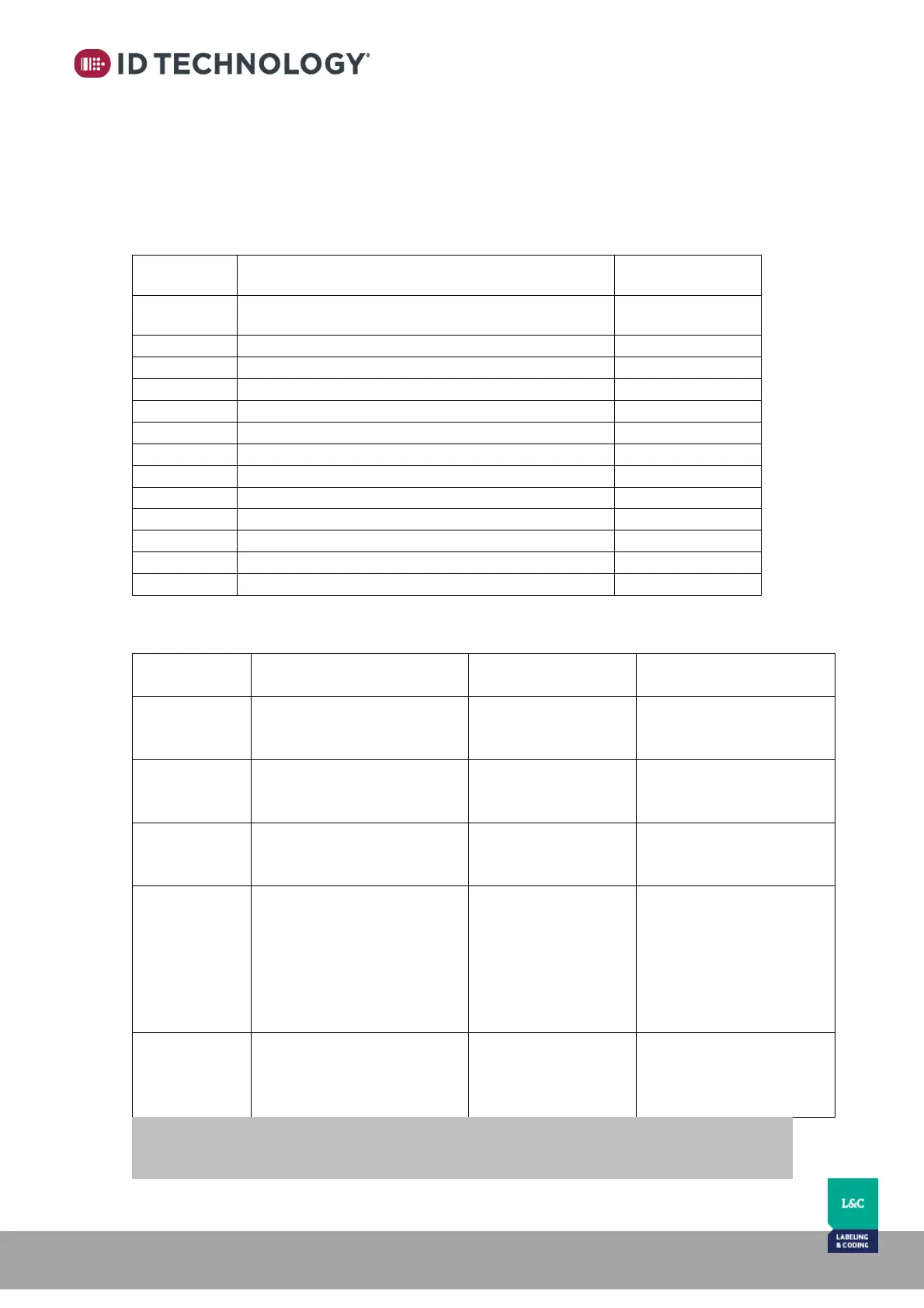
The behavior of the Inputs depends on the Print Mode selected:
MODE DISABLED
(User codes)
START: when there is a
trigger, it puts the device in
print mode.
BCD 0: Bit 0 of the
BCD code.
BCD 0: Bit 0 of the BCD
code.
STOP: when there is a
trigger, it puts the device in
pause.
BCD 1: Bit 1 of the
BCD code.
BCD 1: Bit 1 of the BCD
code.
Reset User Counter: when
there is a trigger, it resets the
user counter.
BCD 2: Bit 2 of the
BCD code.
BCD 2: Bit 2 of the BCD
code.
Reset print direction: when
there is a trigger, it activates
the print direction as
configured.
BCD 3: Bit 3 of the
BCD code.
BCD3 or Reset print
direction: Depending on
the configuration of the
Strobe signal, this bit is
used as BCD3 or Reset
print direction. See note
below.
Invert print direction:
When there is a trigger, it
inverts the print direction.
STROBE: BCD code
validation strobe.
STROBE + Invert:
BCD code validation
strobe and invert the print
direction.
NOTE: In MODE 2, the INPUT 3 is used as BCD3 if Strobe signal is configured as Edge or as
Reset print direction if strobe signal is configured as State.