FC6A S
ERIES
M
ICRO
S
MART
A
LL
-
IN
-O
NE
T
YPE
U
SER
’
S
M
ANUAL
FC9Y-B1722 3-19
3: I
NSTALLATION
AND
W
IRING
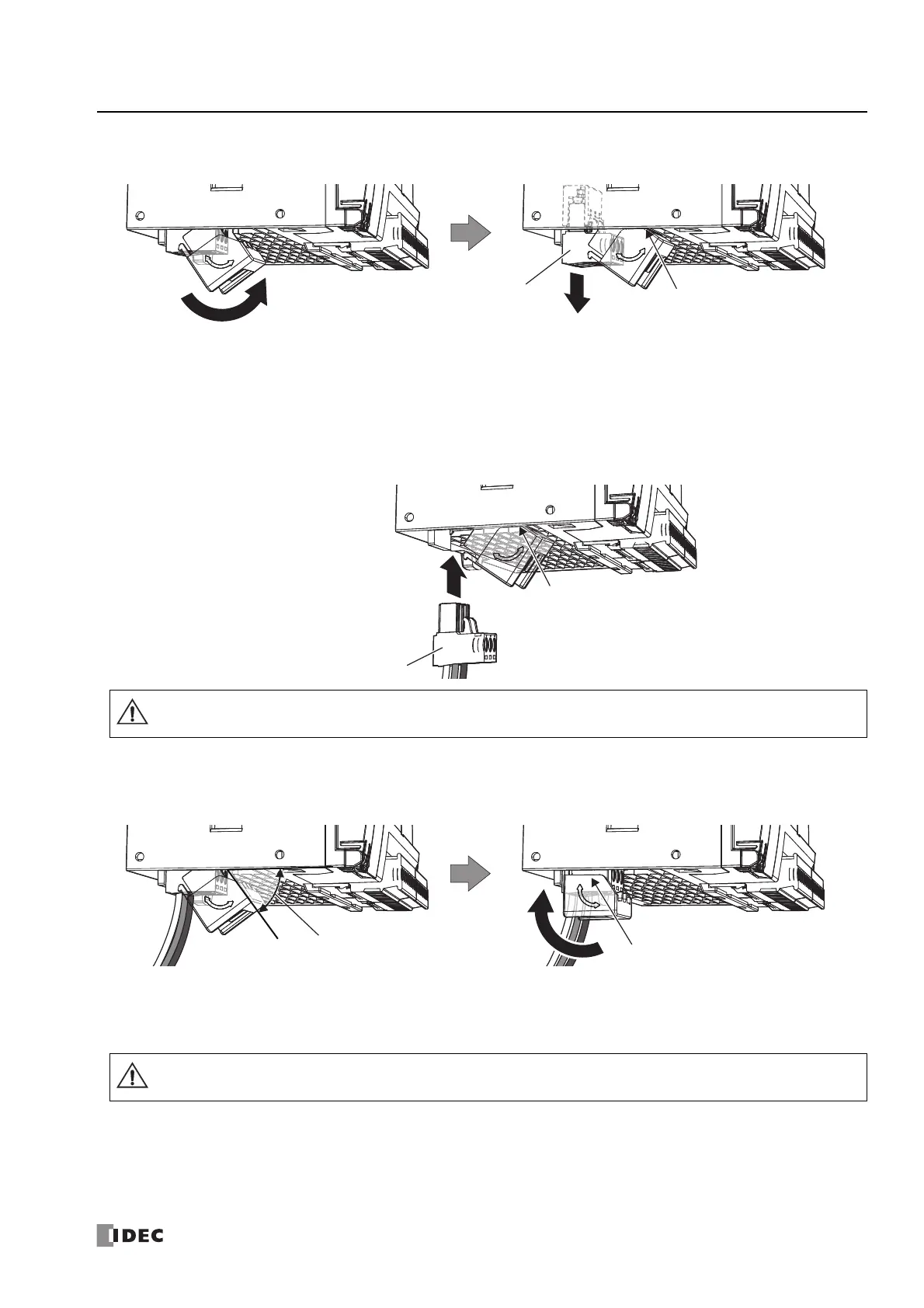
2. Rotate the power supply terminals cover until it touches the CPU module to unlock it, and then remove the power supply
terminals.
Notes:
• Rotate the power supply terminals cover in the direction of the arrow printed on the side.
• The power supply terminals move together with the power supply terminals cover when it is rotated.
■ Attaching the Power Supply Terminals
1. With the power supply terminals cover touching the CPU module, slowly push the power supply terminals with the attached
power line straight into their original position.
2. When the power supply terminals cover is rotated 45° or more from the CPU module, slowly rotate it in the direction of the
arrow until it stops.
The power supply terminals cover and the power supply terminal block are locked.
Notes:
• Rotate the power supply terminals cover in the direction of the arrow printed on the side.
• The power supply terminals move together with the power supply terminals cover when it is rotated.
Power Supply Terminals
Rotate the power supply
terminals cover until it
touches the CPU module
Power supply terminals cover
touching the CPU module
Power Supply Terminals
Push the power supply terminals straight in relation to the CPU module. If you push them in at an angle, there is a risk of
damage or poor contact.
Push the power supply terminals straight in relation to the CPU module. If you push them in at an angle, there is a risk of
damage or poor contact.