3: I
NSTALLATION
AND
W
IRING
3-30 FC6A S
ERIES
M
ICRO
S
MART
A
LL
-
IN
-O
NE
T
YPE
U
SER
’
S
M
ANUAL
FC9Y-B1722
Connection Restrictions for Expansion Modules and Option Modules
Connection Restrictions for Expansion Modules
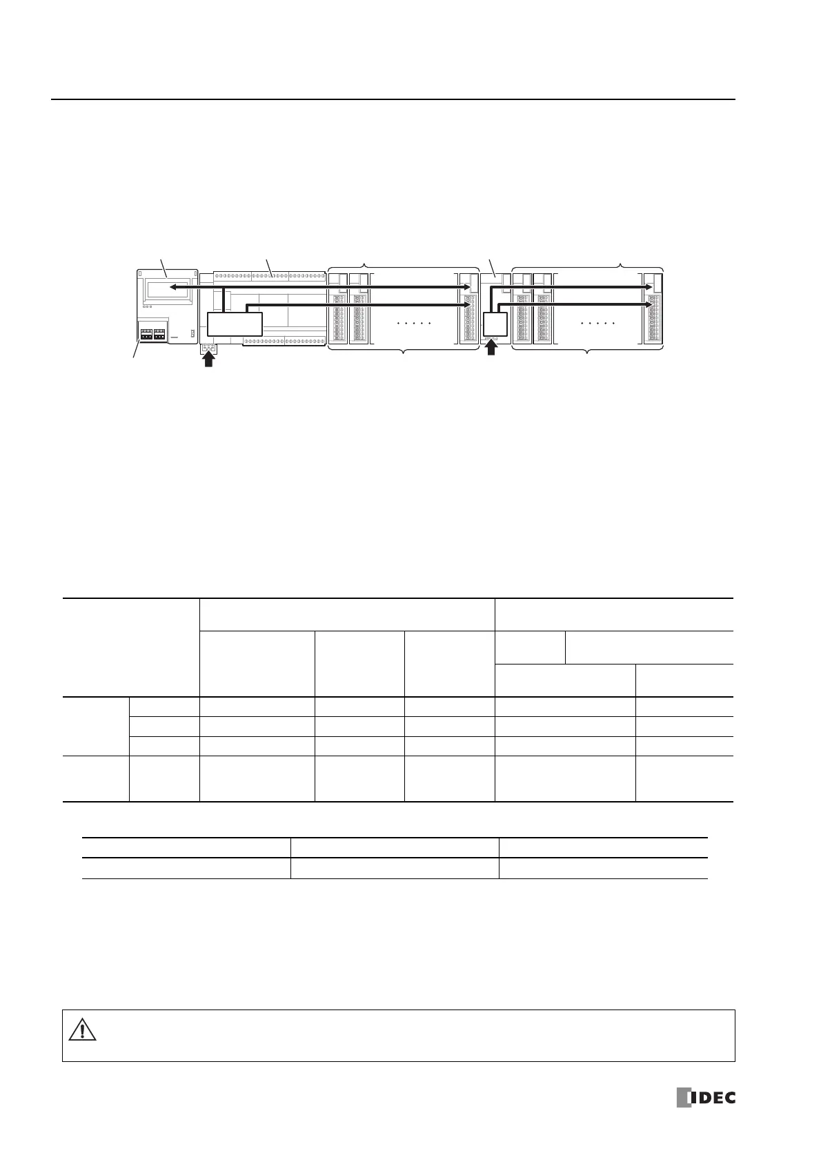
Expansion modules, the HMI module, and cartridges on the basic expansion side operate with the internal power supply that is
supplied from the CPU module. Expansion modules on the expansion interface side operate with the internal power supply that is
supplied from the expansion interface module.
The internal power supply current that can be supplied from the CPU module to the expansion modules, the HMI module, and
cartridges on the basic expansion side varies according to the CPU module. Ensure that the total amount of current for the
expansion modules, the HMI module, and cartridges on the basic expansion side does not exceed the limit of the internal power
supply that can be supplied from the CPU module.
Notes:
• A maximum of eight expansion modules can be connected on the expansion interface side, regardless of the internal power supply current
that can be supplied from the CPU module.
• Expansion modules require an I/O external power supply.
The internal power supply current that can be supplied from the CPU module to the expansion modules, the HMI module, and
cartridges on the basic expansion side is as follows.
*1 The number of modules and cartridges that can be connected on the basic expansion side does not include the expansion interface module.
When using the expansion interface module, add the following current.
*2 The maximum number of cartridges that can be connected to cartridge slots 1, 2, and 3
*3 The internal power supply for the internal 5 V line is used to run the expansion modules (basic expansion side), the HMI module, and the
cartridges. Calculate the total current that is used by the modules and ensure that the limit is not exceeded. For details, see "Internal Power
Supply Current of the Expansion Modules and Option Modules" on page 3-31.
*4 The internal power supply for the internal 24 V line is used to drive the output module relays and transistors. Calculate the total current when
the outputs are simultaneously ON with the following values as the current per output and ensure that the limit is not exceeded.
• Relay output: 6 mA/point
• Transistor output: 1.5 mA/point
CPU Module
Maximum Number of Modules That Can Be Connected
to the CPU Module
Internal Power Supply Current That Can Be
Supplied from the CPU Module
Expansion Modules
(basic expansion
side)
*1
HMI Module Cartridges
*2
Cartridges
Expansion Modules
(basic expansion side)
Internal 5 V Line
Total
*3
Internal 24 V
Line Total
*4
All-in-One
Type
16-I/O Type
412≤ 695 mA ≤ 126 mA
24-I/O Type
712≤ 890 mA ≤ 167 mA
40-I/O Type
713≤ 1,070 mA ≤ 270 mA
CAN J1939
All-in-One
Type
40-I/O Type
713≤ 960 mA ≤ 270 mA
Module Type Model Internal 5 V Line Current
Expansion interface module
FC6A-EXM2
20 mA
Main Power Supply
Power Supply
Expansion ModulesCPU ModuleHMI Module
Expansion Interface Module
(FC6A-EXM2)
Expansion Modules
Cartridges Basic Expansion Side
Power
Supply
Main
Power Supply
Internal 5 V Line
Internal 24 V Line
Internal 5 V Line
Internal 24 V Line
Expansion Interface Side
The CPU module cannot detect the internal power supply current that the expansion modules are using. Observe the
restrictions in this section because malfunction or failure may result if the FC6A Series MicroSmart is continuously used
when the current exceeds the limit.
Caution