FC6A S
ERIES
M
ICRO
S
MART
A
LL
-
IN
-O
NE
T
YPE
U
SER
’
S
M
ANUAL
FC9Y-B1722 A-15
A
PPENDIX
Wiring Example
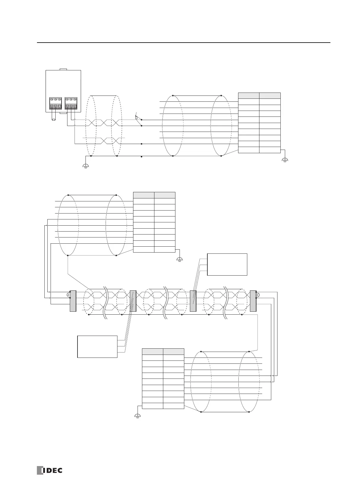
When Connecting the CPU Module via RS485
Wiring example when connecting CPU modules via RS485
We do not recommend connecting the SG line using a shielded cable.
Since the shield of the "FC6A-KC1C external device/O/I connection cable" will be connected to FE (or PE) of the CPU module, one
end of the shield will be grounded when connected to FE (or PE) of the CPU module.
When communication quality is unstable, add terminating resistance matched to the characteristic impedance to both ends of the
cable. Use resistance with a rating of 1/2 W or higher.
FC6A-PC3
RS485
ABSG ABSG
FE
FE
Terminating
Resistance
Terminating
Resistance
Two-pair Two-core Shielded
Twisted-pair Cable
External Device/O/I Communication Cables
(FC6A-KC1C)
Shielded Cable
(8-core, UL-certified Product, CAT 5 or higher)
CPU Module
Serial Port 1
(RJ45 connector)
Shell
Pin
Description
DR
B
A
ER
SD
RD1
2
3
4
5
6
7
8
Shield
NC
SG
White/Orange
Orange
White/Green
Blue
White/Blue
Green
White/Brown
Brown
Two-pair Two-core Shielded
Twisted-pair Cable
Two-pair Two-core Shielded
Twisted-pair Cable
Two-pair Two-core Shielded
Twisted-pair Cable
FE
FE
Terminating Resistance
Terminal Block Terminal Block
Terminal Block
Terminal Block
Terminating Resistance
External Device/O/I Communication Cables
(FC6A-KC1C)
Shielded Cable
(8-core, UL-certified Product, CAT 5 or higher)
Pin
DR
B
A
ER
SD
RD
CPU Module*
1
Serial Port 1
(RJ45 connector)
Shell
Description
1
2
3
4
5
6
7
8
Shield
NC
SG
White/Orange
Orange
White/Green
Blue
White/Blue
Green
White/Brown
Brown
External Device/O/I Communication Cables
(FC6A-KC1C)
Shielded Cable
(8-core, UL-certified Product,
CAT 5 or higher)
CPU Module*
1
Serial Port 1
(RJ45 connector)
CPU Module*
1
CPU Module*
1
Shell
Pin
Description
DR
B
A
ER
SD
RD1
2
3
4
5
6
7
8
Shield
NC
SG
White/Orange
Orange
White/Green
Blue
White/Blue
Green
White/Brown
Brown
*1 The wiring for Serial Port 1 (RJ45
connector) on the CPU module is
entirely the same.