54 iDirect Evolution 8000 Series Satellite Router Installation and Safety Manual
Hardware Connections for a Mobile Remote
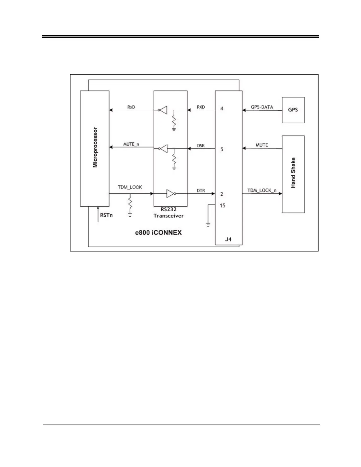
6.2 Hardware Connections for a Mobile Remote
A diagram depicting the iCONNEX e800 hardware connections is shown in Figure 27.
Figure 27. iCONNEX e800 Hardware Connections Diagram
The diagram illustrates the connections needed from GPS receiver and the Handshake device
to the e800 iCONNEX HD-15 GPIO port. The signals shown in the figure have the following
meaning:
• MUTE = 1 the transmitter is muted
= 0 the transmitter is enabled
• TDM_LOCK_n = 0 when the receiver is locked
= 1 when the reciver is unlocked
• GPS-DATA is the data from the GPS receiver
The RJ-45 console port does not support GPS data input or antenna control handshaking
signals. These signals are supported by the HD-15 GPIO port.