iDirect Evolution 8000 Series Satellite Router Installation and Safety Manual 25
Defining the e8350 Satellite Router Rear Panel
The pin assignments for the RS-232 serial connector are defined in Table 11.
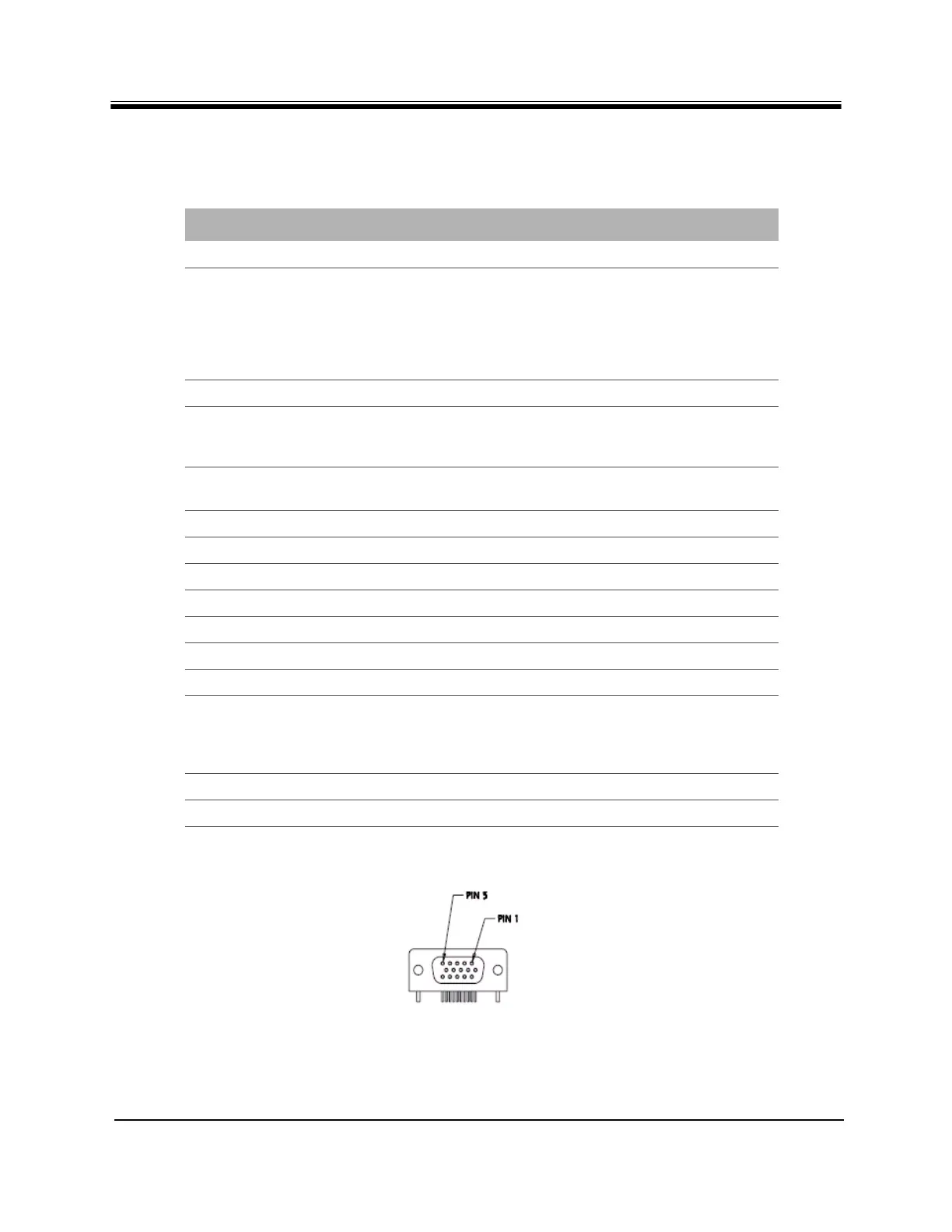
A diagram of the pin numbering scheme is shown in Figure 8.
Figure 8. GPIO/RS-232 Port Pin Numbering
Table 11. RS-232 Serial Connector Pin Assignments
PIN SIGNAL NAME DESCRIPTION
1 +3.3 VDC 200 mA maximum
2 Receive Lock RS-232 voltage level compliant transmit
output signal for antenna control devices.
Receive lock indicates a successful
downstream lock state. In SCPC mode, this
signal means TDM Lock. In DVB-S2 mode, this
signal means NCR Lock.
3 Reserved Future Transmit Data (TxD)
4 Receive Data (RxD) RS-232 voltage level compliant receive data
input signal for connection to a GPS receiver
in mobile applications
5 Transmit Mute RS-232 voltage level compliant receive signal
for use with antenna control devices
6 Reserved Do not connect
7 Not Connected Do not connect
8 Not Connected Do not connect
9 Reserved Do not connect
10 Reserved Do not connect
11 Reserved Do not connect
12 Reserved Do not connect
13 Receive Signal Strength
Indicator (RSSI)
DC voltage level output (0-4.6 VDC) used in
antenna pointing applications to provide
receive composite power measurement or
receive C/N measurement
14 Reserved Output Do not connect
15 Ground (GND) Ground