14 iDirect Evolution X1 Outdoor Satellite Router Installation and Safety Manual
X1 Outdoor Satellite Router Connectors
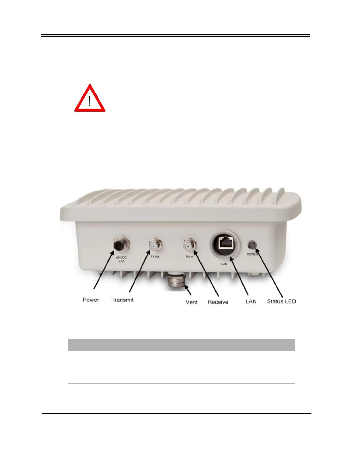
4.1 X1 Outdoor Satellite Router Connectors
The X1 Outdoor Satellite Router interface connectors are shown in Figure 2 and defined in
Table 6. Recommendations for the connectors and cables are further specified in Table 7 on
page 16. The reset button is shown in Figure 3 on page 15 and is housed above the LAN
connector.
Figure 2. X1 Outdoor Router Panel
CAUTION Install where access to the connectors is
unobstructed.
Table 6. iDirect Evolution X1 Outdoor Satellite Router Panel
Label Connector Type Interface and Purpose
Power AC or DC Power
TX Out 75 ohm, F-Type L-Band Transmit signal to Block Up Converter
(BUC) capable of 10 MHz Reference and +24 VDC @
1.5 Amps maximum over operating temperature