16 iDirect Evolution X1 Outdoor Satellite Router Installation and Safety Manual
Power Module Unit Connectors
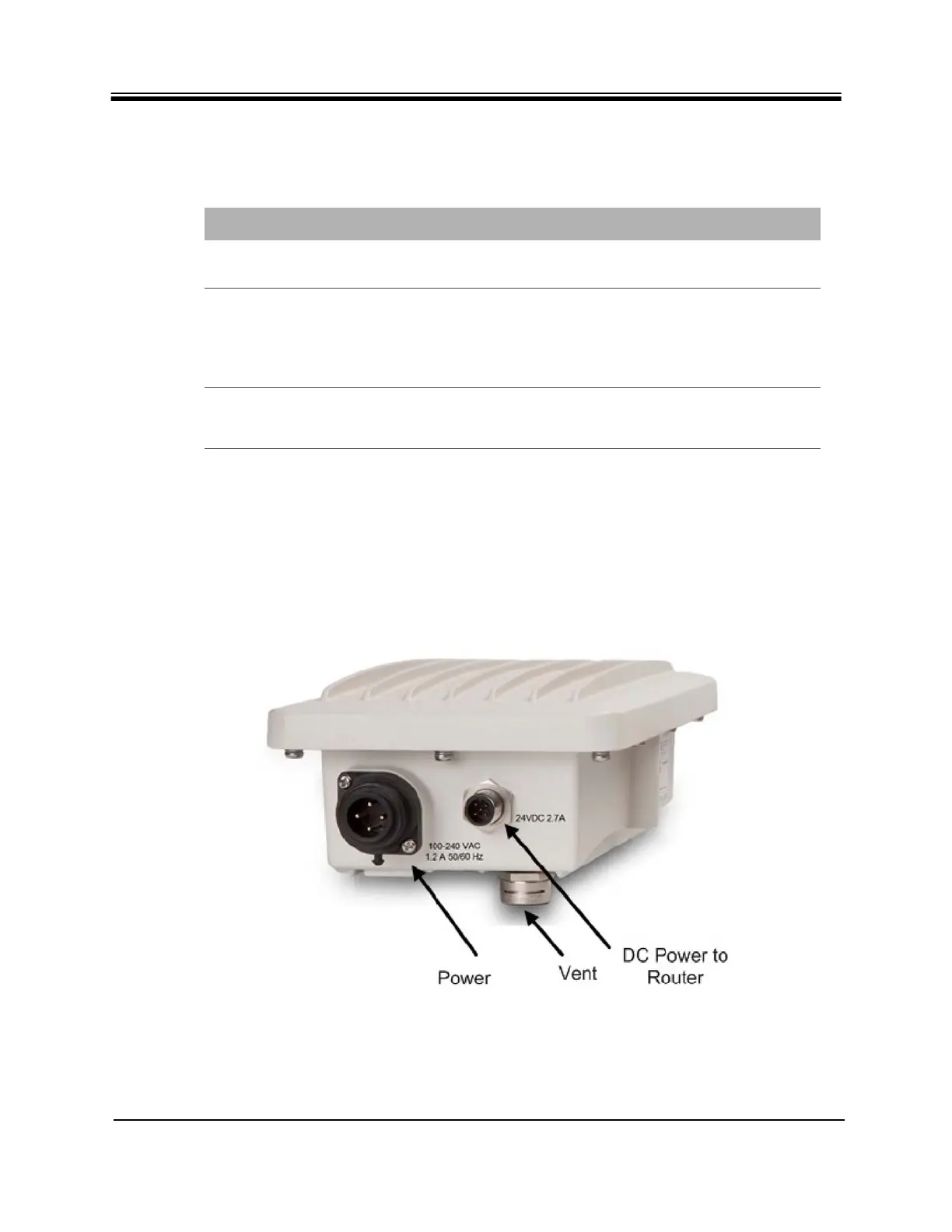
4.2 Power Module Unit Connectors
The Power Module interface connectors are shown in Figure 4 and the pin assignments for the
AC power connector are defined in Table 8 on page 17.
Figure 4. Power Module with Connectors Labeled
Table 7. X1 Outdoor Router Connector-Cable Cross-Reference
Connector Label Connector Type Cable Type
Power Supplied with order DC power cable supplied with
order
TX Out and RX in Either a standard (crimp type) F
connector and wrapping it with
weatherproof tape
or a waterproof (compression
type) F connector
Coax RG 6 or RG 11
LAN (Ethernet) RJ45, protected with an M25
Cable Gland (gland only supplied
with order)
Cat 5-Cat7