iDirect Evolution X1 Outdoor Satellite Router Installation and Safety Manual 17
Ethernet Cable Pinout Details
4.3 Ethernet Cable Pinout Details
To determine the type of RJ-45 cable, examine the sequence of the colored wires as follows:
• Straight through — The colored wires are in the same sequence at both ends of the cable.
• Crossover — The first (far left) colored wire at one end of the cable is the third colored
wire at the other end of the cable, and the second colored wire at one end of the cable is
the sixth colored wire at the end of the cable.
Table 9 lists the pinouts for the Ethernet port and Figure 5 shows the pin order.
Figure 5. RJ-45 Cable Connectors, Plug and Receptacle
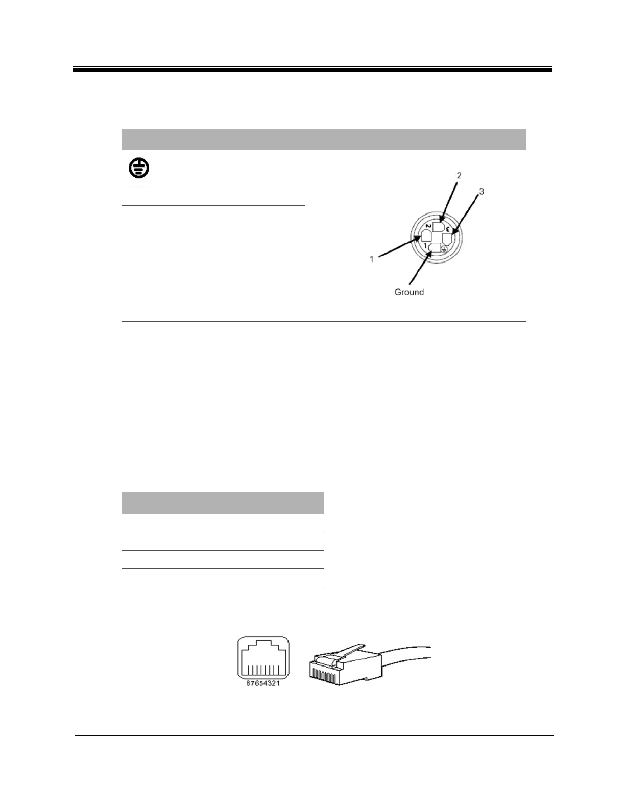
Table 8. Pin Assignments for AC Power Module Gland (4 pin)
Pin Definition Diagram
Ground
1
L - Live
2
(not used)
3
Neutral
Table 9. Ethernet Port Pinouts
RJ-45 Pin Description
1
Tx+
2
Tx-
3
Rx+
6
Rx-