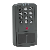
prox.pad Installation/Programming Manual
List of Illustrations
Figure 1: prox.pad Wiring Harness........................................................................................................15
Figure 2: Identifying Pin Connectors.....................................................................................................16
Figure 3: Performing a Wall Mounted Installation.................................................................................19
Figure 4: Performing a Glass Mounted Installation...............................................................................20
Figure 5: Performing a Secure Installation............................................................................................22
Figure 6: Tamper Switch Locations.......................................................................................................23
Figure 7: Removing/Inserting Printed Circuit Board..............................................................................24
Figure 8: Program Button Location on Main Circuit Board....................................................................25
Figure 9: Wiring the Aux Relay for Alarm Shunt Operation...................................................................28
Figure 10: Wiring the Aux Relay for Forced Door Alarm.......................................................................29
Figure 11: Wiring the Aux Relay for Propped Door Alarm....................................................................30
Figure 12: Wiring the Door Contact Input..............................................................................................31
Figure 13: Wiring the REX Switch.........................................................................................................32
Figure 14: Electric Strike (Fail Secure) Wiring......................................................................................33
Figure 15: MagLock (Fail Safe) Wiring Diagram...................................................................................33
Figure 16: Wiring to a Wiegand Panel...................................................................................................60
Figure 17: Wiring the prox.pad to the Secured Series DCM.................................................................70
Document # 6055676, Rev 2.2, D4b Page 7 of 86

 Loading...