List
of
Figures
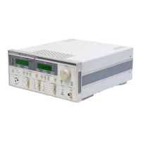
LDC-3722B Front Panel
.....................................................................................................
2-3
................................................................................
LDC-3700 Series TEC MODE Section 2-8
LDC-3700 Series TEC DISPLAY Switch Section
................................................................
2-9
..........................................................................
LDC-3700 Series PARAMETER Section 2-10
LDC-3700 Series TEC Error Section
.................................................................................
2-13
.........................................................................
LDC-3700 Series LASER MODE Section
2-14
.........................................................
LDC-3700 Series LASER DISPLAY Switch Section
2-15
..........................................................................
LDC-3700 Series PARAMETER Section 2-16
....................................................................................................
LASER Error Inlcators 2-18
.......................................................................................
LDC-3700 Series MOD Sections 2-19
............................................................................................
LDC-3700 Series Back Panel 2-20
............................................................................................
Back Panel TEC Connector 221
.................................................................................................
Back Panel LD Connector 2-22
..................................................................
Common Laser Cathode
-
Photodiode Cathode
2-23
....................................................................
Common Laser Cathode
-
Photodiode Anode
2-23
....................................................................
Common Laser Anode
-
Photodiode Cathode
2-24
.......................................................................
Common Laser Anode
-
Photodiode Anode
2-24
......................................................................................
White Space Syntactic Diagram 3-3
<PROGRAM MESSAGE TERMINATOR>
Syntax
Diagram
..............................................
3-4
<PROGRAM MESSAGE UNIT SEPARATOR> Syntax Diagram
.......................................
3-4
...................................................
<PROGRAM HEADER SEPARATOR> Syntax Diagram
3-3
...................................................
<compound command program header> Syntax Diagram
3-5
..........................................................
<compound query program header> Syntax Diagram
3-6
..........................................
<ARBITRARY
BLOCK PROGRAM DATA> Syntax Diagram
3-7
........................................................
<PROGRAM DATA SEPARATOR> Syntax Diagram
3-7
Standard Event Status RegisterIStandard Event Status Enable Register
.............................
3-12
........................................................................................
Service Request Enable Register 3-20
LDC-3700 Series Status Reporting Schematic Diagram
.....................................................
3-26
LDC-3700 Series Laser Diode Controller LASER Output
Off
Register
..............................
3-29
...................................
LDC-3700 Series Laser Diode Controller TEC Output
O£f
Register
3-30
Command Description Format
...........................................................................................
4-8
LDC-3700 Series Laser Diode Controller Command Path Structure
....................................
4-9
....................................................
LDC-3700 Series Laser Diode Controller Block Diagram
5-1
.................................................................................................
TEC Board Block Diagram 5.2
.............................................................................................
LASER Board Block Diagram
5-6
.................................................................................
Main Processor Board Block Diagram
5-7
..........................................................................
Front Panel Display Board Block Diagram
5-9
Front Panel Switch Board Block Diagram
...........................................................................
5-9
.................................................................................
Power Supply Board Block Diagram
5-11
.......................................................................................................
I
Calibration Circuit 6-12
pd
............................................................................................
Pourer Line Voltage Selection 6-16
........................................................................
Thermistor Resistance Versus Temperature A-2
Thermistor Temperature Range
..........................................................................................
B-2
...........................................................................................................
AD590
Nonlinearity C-2
Artisan Technology Group - Quality Instrumentation ... Guaranteed | (888) 88-SOURCE | www.artisantg.com

 Loading...