2.6.1
Automatic Set Point Adjustment
If
the ADJUST knob is turned during operation, whle a measured
TEC
value is being displayed and the
(ADJUST)
TEC
switch is selected. the TEC display will indicate the set point of the selected operating mode (T,
R,
or
ITE)
This control mode set point display will continue for three seconds, and then the display will revert to its
former state (a measured value).
For
esaniple. assume that (ADJUST) TEC mode is in effect and
T
is selected as the TEC MODE, but the (TEC
DISPLAY) R snitch is selected and the sensor (thermistor) resistance is &splayed on the TEC display.
If
the
ADJUST knob is turned, the TEC display will then show the temperature set point for
3
seconds. After
3
seconds
the TEC display will revert to showing the measured R value.
Likewise. if the ADJUST knob is turned during operation, while a measured LASER value (I, IpD, or PpD) is being
displayed and the (ADJUST) LASER switch is selected and the (LASER MODE) ON switch is off, the LASER
displn! will indicate the set point of the selected operating mode
(I/IHBW
or
P).
This control mode set point display
\\.ill
continue for
3
seconds, and then the display will revert to its former state
(a
measured value).
For eznmple, assume that (ADJUST) LASER mode is in effect, the (LASER MODE) ON switch is off, and
I
is
selected as the LASER MODE, but
IpD
is selected in the LASER DISPLAY switch section and the photodiode
current is displa!cd on the LASER display.
If
the ADJUST knob is turned, the LASER display will then show the
LASER current set point for three seconds. After three seconds the LASER display will revert to showing the
measured
IpD
\due.
Notc.
In
the LASER DISPLAY snitch section, the IpD and PpD display modes both correspond to the P control
mode. ivhlle the
I
display mode corresponds to either
I
or
IHBW
control modes of the LASER MODE section.
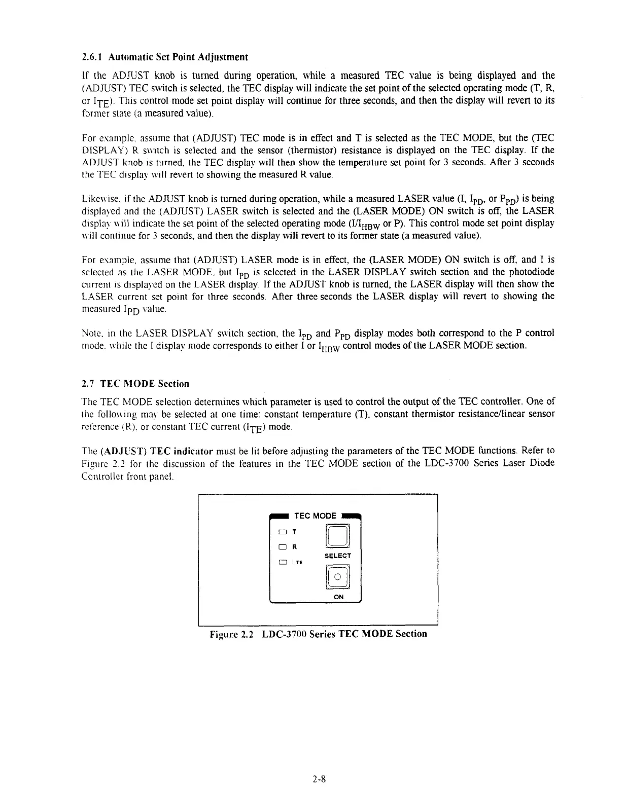
2.7
TEC MODE
Section
The TEC MODE selection determines which parameter is used to control the output of the TEC controller. One of
the follo\i.ing rnny be selected at one time: constant temperature (T), constant thermistor resistancellinear sensor
reference
(R).
or constant
TEC
current
IT^)
mode.
The (ADJUST) TEC
indiciitor
must be lit before adjusting the parameters of the TEC MODE functions. Refer to
Figire
2.2
for the discussion of the features in the TEC MODE section of the LDC-3700 Series Laser Diode
Controller front panel.
TEC
MODE
a
Figure
2.2
LDC-3700
Series
TEC MODE
Section
Artisan Technology Group - Quality Instrumentation ... Guaranteed | (888) 88-SOURCE | www.artisantg.com

 Loading...
