This chapter explains the general function of each board and each circuit in the block diagram. The
TEC
theory
of
operation is explained in Section
5.2,
the LASER side is explained in Section
5.3,
and the theory,of operation of
the Main Processor board, which is common to both TEC and LASER operation, is explained in Section
5.4.
The
Front Panel Display and Switch Boards are discussed in Section
5.5,
while the Power Supply Board is discussed in
Section
5.6.
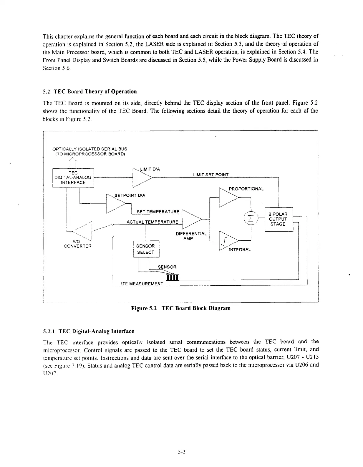
5.2
TEC Board Theory of Operation
The
TEC
Board is mounted on its side, directly behind the TEC display section of the front panel. Figure
5.2
shows the functionality of the TEC Board. The following sections detail the theory of operation for each of the
blocks in Fipre
3.2.
OPTICALLY ISOLATED SERIAL BUS
(TO
MICROPROCESSOR BOARD)
DIGITAL-ANALOG
LIMIT SET POINT
INTERFACE
L-
,
I
SET TEMPERATURE
ACTUAL TEMPERATURE
\I
A/
D
CONVERTER
DIFFERENTIAL
AMP
SENSOR
PROPORTIONAL
-Dl,
4w
INTEGRAL
BIPOLAR
OUTPUT
STAGE
ITE MEASUREMENT
I
Figure
5.2
TEC
Board Block Diagram
5.2.1
TEC
Digital-Analog
Interface
The
TEC
interface provides optically isolated serial communications between the
TEC
board and the
n~icroprocessor. Control signals are passed to the TEC board to set the TEC board status, current limit, and
temperature
set
points. Instructions and
data
are sent over the serial interface to the optical barrier,
U207
-
U213
(see
Figure
7
19).
Status and analog TEC control data are serially passed back to the microprocessor via
U206
and
U207.
Artisan Technology Group - Quality Instrumentation ... Guaranteed | (888) 88-SOURCE | www.artisantg.com

 Loading...
