When the unit is powered-up, the parameters will automatically be restored to the same
values that were present at the last power-down. Furthermore, all of the saved setups
\+dl be "remembered", and easily recalled.
2.4.1.2
TEC
Functions
This section gives a brief synopsis of the TEC controller sections on the LDC-3700 Series Laser Diode Controller
front panel
I
I
c
ll,
SELECT
1_?1
}I
TEC
DISPLAY
-q
T
R
In
SET
TEC
PARAMETER
LASER
S@.ECT
.
TEC
I
-
c
TEMP
LIMT
z
TE
CURRENT
Lwn
-100%
ln
C
SENSOR OPEN
3
T€
MODULE
OPEN
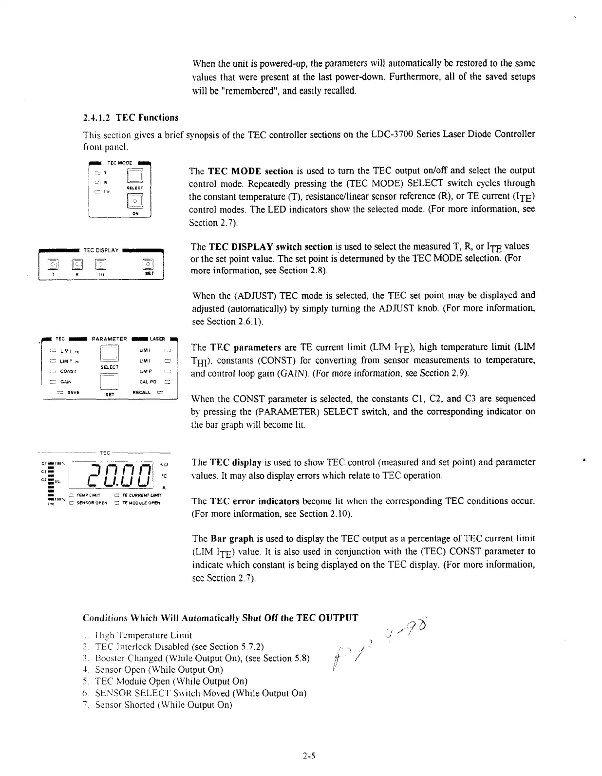
The
TEC
MODE
section
is used to
turn
the TEC output onloff and select the output
control mode. Repeatedly pressing the (TEC MODE) SELECT switch cycles through
the constant temperature (T),
resistancellinear sensor reference
(R),
or TE current
(ITE)
control modes. The LED indicators show the selected mode. (For more information, see
Section
2.7).
The
TEC
DISPLAY
switch section
is used to select the measured
T,
R,
or
ITE
values
or the set point value. The set point is'determined by the TEC MODE selection. (For
more information, see Section 2.8).
When the (ADJUST) TEC mode is selected, the TEC set point may be displayed and
adjusted (automatically) by simply turning the ADJUST knob. (For more information,
see Section 2.6.1).
The
TEC
parameters
are TE current limit
(LIM
ITE),
high temperature limit (LIM
THI). constants (CONST) for converting from sensor measurements to temperature,
and control loop gain (GAIN). (For more information, see Section 2.9).
When the
CONST parameter is selected, the constants C1, C2, and C3 are sequenced
by pressing the
(PARAMETER)
SELECT switch, and the corresponding indicator on
the bar graph will become lit.
The
TEC
display
is used to show
TEC
control (measured and set point) and parameter
values. It may also display errors which relate to
TEC
operation.
The
TEC
error indicators
become lit when the corresponding TEC conditions occur.
(For more information, see Section 2.10).
The
Bar graph
is used to display the TEC output as a percentage of TEC current limit
(LIM
1~~)
value. It is also used in conjunction with the (TEC) CONST parameter to
indicate which constant is being displayed on the
EC
display. (For more information,
see Section 2.7).
Conditions
Which Will Automatically
Shut
Off
the
TEC OUTPUT
"-,
3
H~gh Tcniperature L~rn~t
,CfJ
TEC
In~erlock D~sabled (see Sect~on
5
7
2)
7
Booster Changed (Wh~le Output On), (see Section
5
8)
,").
'i
Sensor Open (Wh~le Output On)
1
TEC
Module Open (While Output On)
SENSOR
SELECT Sn.ilch Moved (While Output On)
Sensor Shorted (While Output On)
Artisan Technology Group - Quality Instrumentation ... Guaranteed | (888) 88-SOURCE | www.artisantg.com

 Loading...
