2.1.1.3
LASER Functions
This section gives a brief synopsis of the LASER controller sections on the LDC-3700 Series Laser Diode
Controller front panel. For more detailed information,
see
sections 2.11
-
2.16.
LASER MODE
I
I
0
0
P
SELECT
0
Irnw
ON
LASER DISPLAY-b
TEC
B
PARAMETER
B
LASER
1
0
LIM
l
n
0
LIM T
u
:::
:
z
SELECT
D
CONST
LIM
P
O
O
GAIN
CALPD
0
O
SAM
SEI
RECALL
0
USER
0
500
mA
PRESS TWICE
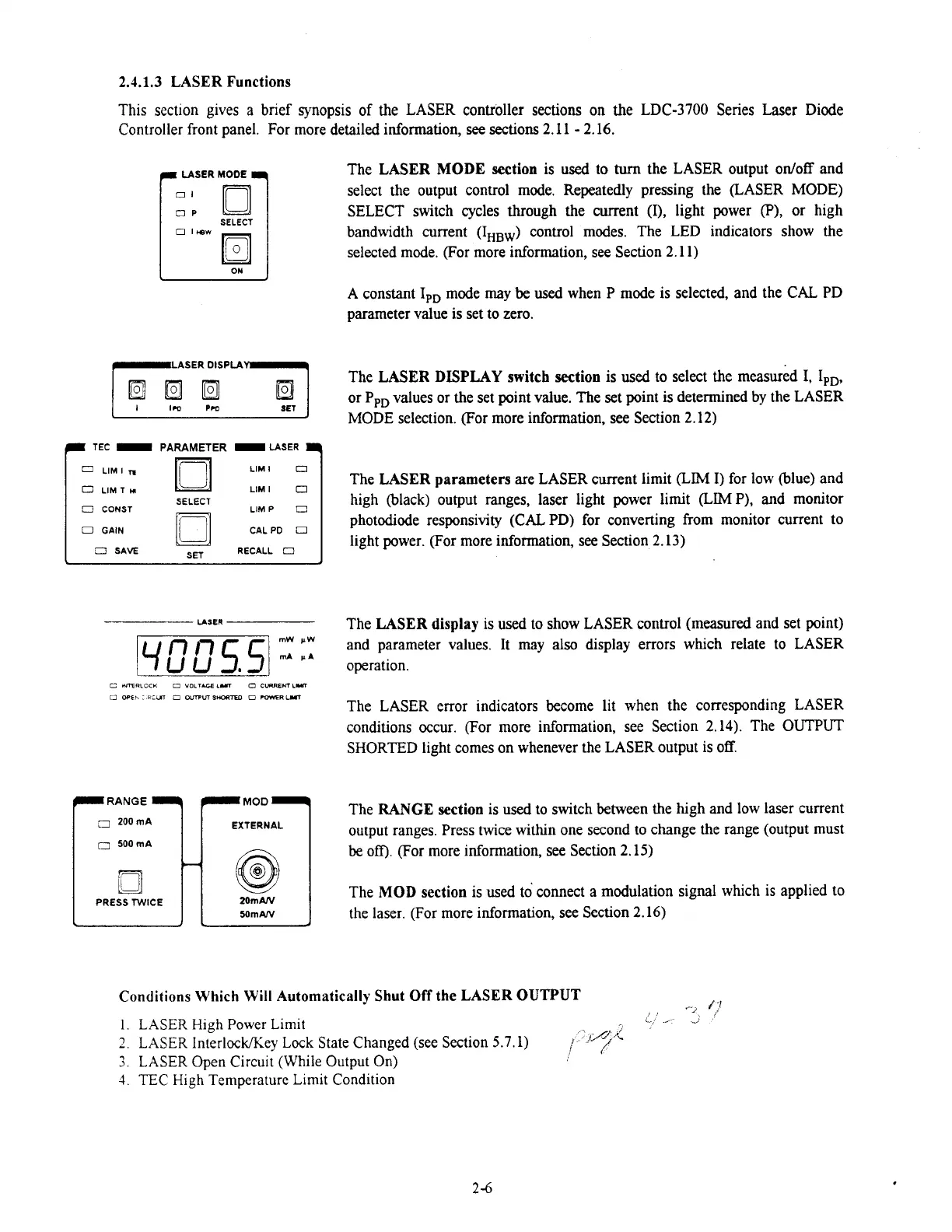
The LASER
MODE
section is used to
turn
the LASER output odoff and
select the output control mode. Repeatedly pressing the (LASER MODE)
SELECT switch cycles through the current (I), light power
(P),
or high
bandwidth current (IHBW) control modes. The LED indicators show the
selected mode. (For more information, see Section 2.11)
A constant IpD mode may
be
used when
P
mode is selected, and the CAL
PD
parameter value is set to zero.
The LASER
DISPLAY
switch section is used to select the measured I, IPD.
or PpD values or the set point value. The
set
point is determined by the LASER
MODE selection. (For more information, see Section 2.12)
The LASER parameters are LASER current limit
(LIM
I) for low (blue) and
high (black) output ranges, laser light power limit
(LIMP),
and monitor
photodiode responsivity (CAL PD) for converting from monitor current to
light power. (For more information, see Section 2.13)
The LASER display is used to show LASER control (measured and set point)
and parameter values. It may also display errors which relate to LASER
operation.
The LASER error indicators become lit when the
corresponding LASER
conditions occur. (For more information, see Section 2.14). The OUTPUT
SHORTED light comes on whenever the LASER output is off.
The RANGE section is used to switch between the high and low laser current
output ranges. Press twice within one second to change the range (output must
be
off).
(For more information, see Section 2.15)
The
MOD
section is used to connect a modulation signal whlch is applied to
the laser. (For more information, see Section 2.16)
Conditions Which Will Automatically Shut
Off
the LASER
OUTPUT
.-,
i
r
i
1
LASER Hlgh Power Llm~t
i.-
-
)
,.,&;
.c
2
LASER InterlockKey Lock State Changed (see Section 5.7.1)
,
3
LASER Open Circu~t
(While
Output On)
I
TEC
H~gh Temperature Llmlt Cond~tion
Artisan Technology Group - Quality Instrumentation ... Guaranteed | (888) 88-SOURCE | www.artisantg.com

 Loading...
