2.18.3
TEC Grounding Considerations
The TEC outputs of the LDC-3700 Series Laser Diode Controller are isolated from chassis ground;allowing either
output terminal to be grounded at the user's option. The thermistor's
(-)
terminal and the
TEC
module's
(-)
terminals are internally connected.
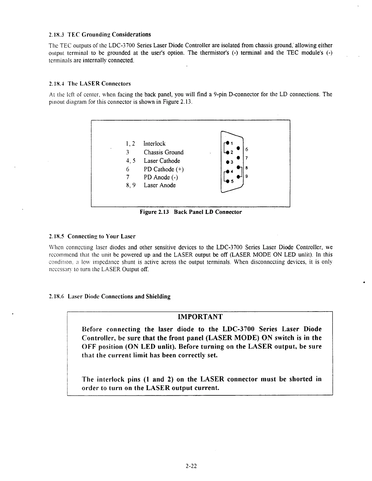
2.18.4
The
LASER
Connectors
At
the lcft of center, u hen facing the back panel, you will find a 9-pin D-connector for the LD connections. The
p~nout diagram for this connector is shown in Figure
2.13.
1,
2
Interlock
3
Chassis Ground
4,
5
Laser Cathode
6
PD Cathode
(+)
7
PD Anode
(-)
8.9
LaserAnode
Figure
2.13
Back
Panel
LD
Connector
2.18.5
Connecting
to
Your Laser
\E'l~cn
connecting
laser d~odes and other sensitive devices to the LDC-3700 Series Laser Diode Controller, we
recommend
that the un~t be powered up and the LASER output
be
off (LASER MODE ON LED unlit). In this
co~~d~t~on.
;I
lo11 ~rnpcdilnce shunt
IS
active across the output temnals. When disconnecting devices, it is only
ncccss:ln. to turn the
LASER
Output off.
2.18.6
Li~scr
Diode
Connections
and
Shielding
IMPORTANT
Before connecting the laser diode to the LDC-3700 Series Laser Diode
Controller, be sure that the front panel (LASER MODE) ON switch
is
in the
OFF
position
(ON
LED unlit). Before tur'ning on the LASER output,
be
sure
thi~t the current limit has been correctly set.
The interlock pins
(1
and
2)
on the LASER connector must be shorted in
order lo turn on the LASER output current.
Artisan Technology Group - Quality Instrumentation ... Guaranteed | (888) 88-SOURCE | www.artisantg.com

 Loading...
