The
IEI13\i,
indicator becomes lit when the unit is in high bandwidth constant current control mode. When constant
JfI,,,,,
mode is selected, the
LASER
output is controlled to the constant
I
set point value.
2.1
1.3
LASER
MODE ON
The
(LASER MODE)
ON
switch is used to
turn
&he
LASER
output on and off. When the
LASER
output is off,
an
internal short is placed across the
LASER
output. This condition is indicated by the
OUTPUT SHORTED
indicator
becoming
lit.
The
(LASER MODE)
ON
switch has a toggling action. Push it once to
turn
the
LASER
output on, and push it
again to turn the
LASER
output off. The output is off when the unit is powered up. The
(LASER MODE)
ON
indicator becomes lit when the
LASER
current output is on. The
LASER
output will drive to the value set by the
corresponding
LASER MODE.
1-
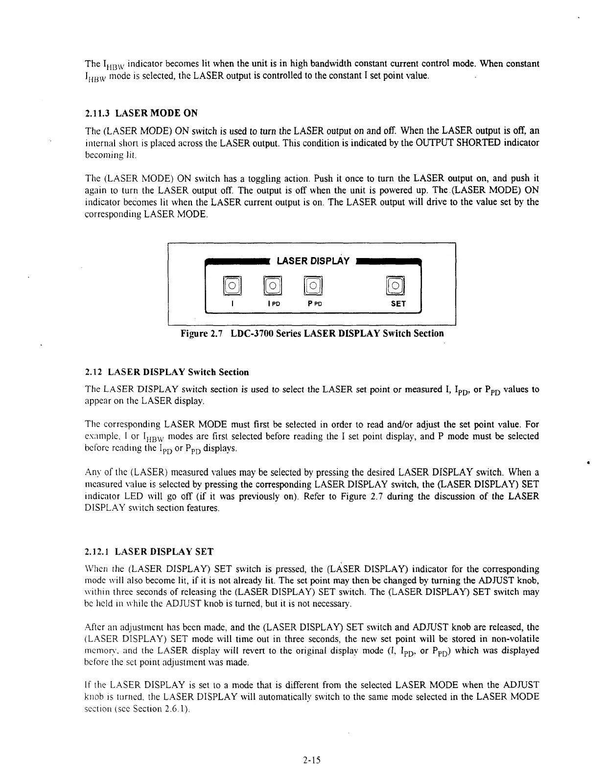
LASER
DISPLAY
1
la
SET
I
Fiyre
2.7
LDC-3700
Series
LASER
DISPLAY
Switch Section
2.1
2
LASER
DISPLAY Switch
Section
The LASER
DISPLAY
switch section is used to select the
LASER
set point or measured
I,
IPD,
or
PPD
values to
appear on the
LASER
display.
The corresponding
LASER MODE
must first
be
selected in order to read andlor adjust the set point value. For
ewnple.
1
or
IIIBW
modes are first selected before reading the
I
set point display, and
P
mode must
be
selected
bcforc read~ng the
IpD
or PPD displays.
Any
of
the
(LASER)
measured ~alues may be selected by pressing the desired
LASER DISPLAY
switch. When a
measured value is selected by pressing the corresponding
LASER DISPLAY
switch, the
(LASER DISPLAY) SET
~ndicator
LED
will go off (if it was previously on). Refer to Figure
2.7
during the discussion of the
LASER
DISPLAY
switch section features.
2.12.1
LASER
DISPLAY SET
\Vhen the
(LASER DISPLAY) SET
switch is pressed, the
(LASER
DISPLAY)
indicator for the corresponding
mode will also become lit, if it is not already lit.
The
set point may then
be
changed by turning the
ADNST
knob,
\\.ithin three seconds of releasing the
(LASER DISPLAY) SET
switch. The
(LASER DISPLAY) SET
switch may
be held in
\\.bile
the
ADJUST
knob is turned, but it is not necessary.
.4fter an adjustment has been made, and the
(LASER DISPLAY) SET
switch and
ADJUST
knob are released, the
(LASER
DISPLAY) SET
mode will time out in three seconds, the new set point will be stored in non-volatile
rnemon.. and the LASER display will revert to the original displav mode
(I,
IpD, or
PPD)
which was displayed
before the set polnt adjustment was made.
If
the LASER
DISPLAY
is set to a mode that is
different
from the selected
LASER MODE
when the
ADNST
knob 1s lurned.
the
LASER DISPLAY
will automatically switch to the same mode selected in the
LASER MODE
section (see Section
2.6.1).
Artisan Technology Group - Quality Instrumentation ... Guaranteed | (888) 88-SOURCE | www.artisantg.com

 Loading...
