3.1.1
Preparation for Bus
Control
To
use
the LDC-3700 Series Laser Diode Controller remotely, you
will
need to
install
an IEEE-488 interface
adapter in your host computer.
These
adapters and
support
software
are
available from several manufacturers and
can
be
installed in most computers. This
manual
assumes
that you
have
a basic knowledge of the GPIBEEE-488
interface
bus
and how to
use
it for instrument control.
This
chapter
also
assumes that you
are
familiar with the
controls on the LDC-3700 Series Laser Diode Controller.
Review
Chapter 2
if
you need more details on how to
operate the LDC-3700 Series Laser Diode Controller.
The
talk
and listen addresses on the LDC-3700 Series Laser Diode Controller
are
identical. This GPIB address is
read locally
by
pressing the GPIB
LOCAL
switch and reading the display. To
set
the GPIB
address,
press
and
hold
in the
(PARAMETER)
SET switch while displaying the GPIB
address.
Turn
the
ADJUST
knob
until the desired
address value is displayed, then release the SET switch The new GPIB
address
will
then
be
stored in non-volatile
memory, independent of the
SAVE
and RECALL "binn number. The allowable
address
range
is
0
-
30 for primary
GPIB
addressing.
It
is
not normally possible
to
exceed
this
range. However,
if
the
GPIB
address
were
to
ed 30,
it
will
not hang up the bus.
If
the GPIB
address
is ever displayed
as
a
value
greater
than
30,
service
of the
LDC-3700 Series Laser Diode Controller would
be
required,
since
this
value
is
normally
limited
by
the
LDC-3700
Series Laser Diode Controller's
lirmware.
Extended GPIB addressing
is
not implemented on the LDC-3700
Series
Laser Diode Controller at
this
time.
3.2 ANSyIEEE-488.2
Definitions
The following sections contain the relevant definitions for syntax
diagrams
and syntax elements for the LDC-3700
Series Laser Diode Controller commands,
as
defined
by
the
IEEE-488.2
standard.
A
complete listing of that
standard is not practical here, but these definitions
are
applicable to the remote operation of the LDC-3700 Series
Laser Diode Controller.
3.2.1
Syntax Diagrams
The syntax diagrams
in
Section
4.4
show the most complete form of command construction, but
they
don't show
every possible construction. Some of the other possibilities which
are
not shown
in
the syntax diagrams of
Section
4.4
are
discussed
in Section 3.5,
Advanced
Programming.
These
syntax
diagrams
conform to the
ANSVLEEE-488.2-1987 standard, and the terminology presented here reflects that standard.
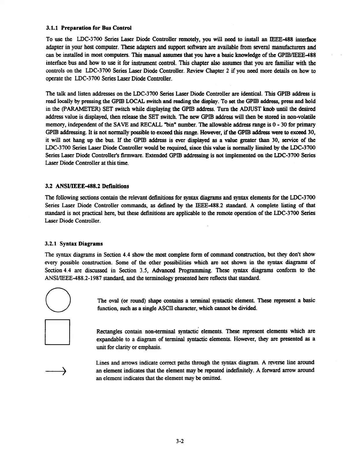
0
The oval (or round) shape contains a
terminal
syntactic element. These represent a basic
function, such
as
a single ASCII character, which cannot
be
divided.
Rectangles contain non-terminal
syntactic'
elements. These represent elements which are
expandable to
a
diagram of terminal syntactic elements. However,
they
are
presented
as
a
unit for clarity or emphasis.
Lines and arrows indicate correct
paths
through the syntax diagram.
A
reverse line around
-+
an element indicates that the element
may
be
repeated
indefinitely.
A
forward arrow
around
an element indicates that the element may
be
omitted.
Artisan Technology Group - Quality Instrumentation ... Guaranteed | (888) 88-SOURCE | www.artisantg.com

 Loading...
