2.18.1
SENSOR SELECT Switch
The
SENSOR
SELECT
snitch is used to select sensor type and, in the case of thermistor sensor, the source current
level. Table
2.1
shows the
SENSOR
SELECT
positions and corresponding position code. When the sensor switch
is changed during
TEC
mode operation, the new sensor position code will
be
indicated on the
TEC
display for
three seconds.
SENSOR SELECT POSITION CODES
I
I
SWITCH POSITION CODE
100 UA
-4
1
10
UA
-42
LM335 -03
AD590 -04
able
2.4
SENSOR
SELECT Switch Positions
The 10 uA and 100 uA designations are for the current source level; thermistor sensor
type
is implied. When using
a thermistor, the supply current depends on the thermistor operating temperature range and the required
temperature resolution. Guidelines for setting this switch are contained in Appendix
B.
The AD590 sensor operates as a current source which is proportional to the sensed temperature. The LM335
sensor operates as a voltage source which is proportional to the sensed temperature. Both of these sensors are
approximately linear over their operating ranges. When they are used, the constants
C1
and
C2
are used for
a
two-
point conversion. For more information on setting the constants for use with these sensors, see Section
2.9.5
and
Appendix
C.
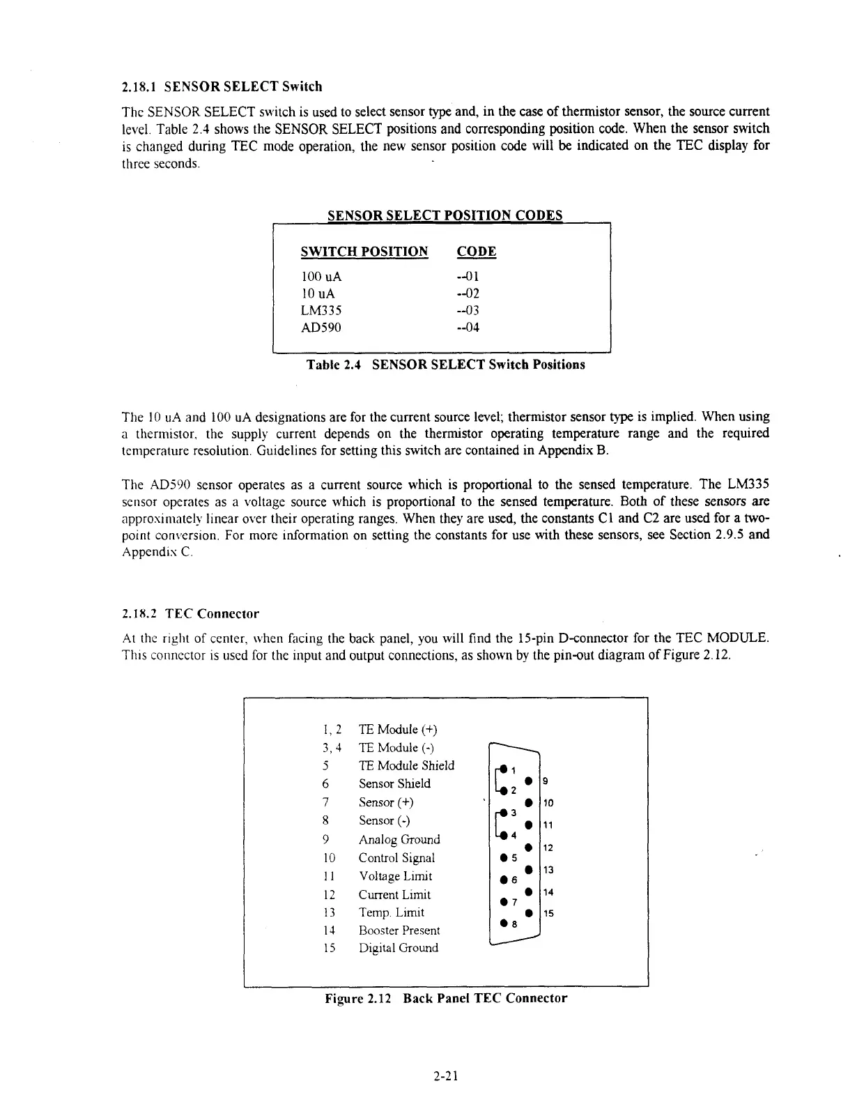
2.18.2
TEC Connector
At thc r~ght of center, when facing the back panel, you will find the 15-pin D-connector for the
TEC
MODULE.
Th~s connector is used for the input and output connections, as shown by the pin-out diagram
of
Figure
2.12.
TE
Module
(+)
TE
Module
(-)
TE
Module
Shield
Sensor Shleld
Sensor
(+)
Sensor
(-)
Analog Ground
Control Signal
Voltage Limit
Current Limit
Temp. Limit
Rooster Present
Digital Ground
Figure
2.12
Back Panel
TEC
Connector
Artisan Technology Group - Quality Instrumentation ... Guaranteed | (888) 88-SOURCE | www.artisantg.com

 Loading...
