Chapter
5
THEORY
OF
OPERATION
5.1
Introduction
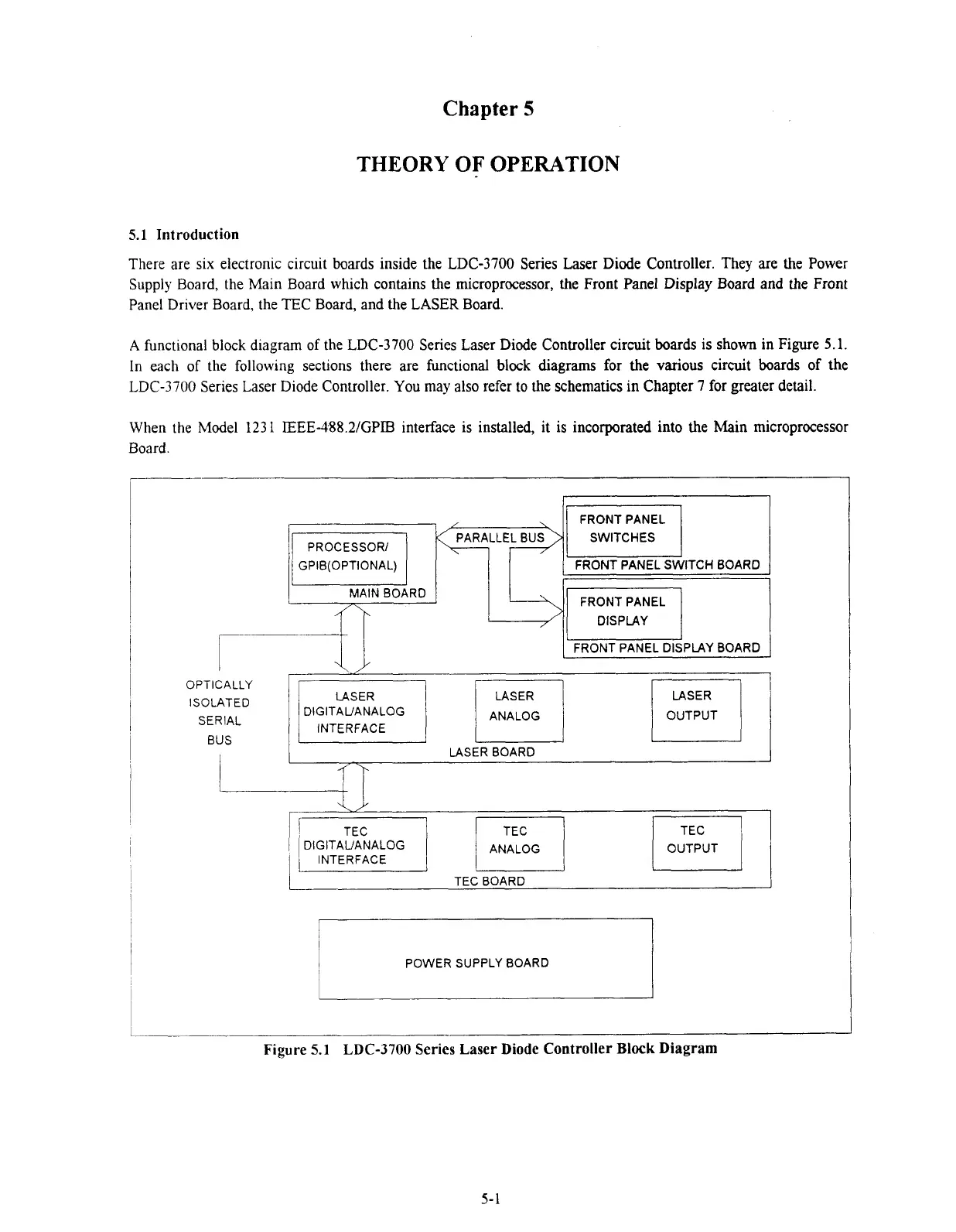
There are six electronic circuit boards inside the LDC-3700 Series Laser Diode Controller. They are the Power
Supply Board, the Main Board wluch contains the microprocessor, the Front Panel Display Board and the Front
Panel Driver Board, the
TEC
Board, and the LASER Board.
A
functional block diagram of the LDC-3700 Series Laser Diode Controller circuit boards is shown in Figure
5.1.
In each of the following sections there are functional block diagrams for
the
various circuit boards of the
LDC-3700
Series Laser Diode Controller. You may also refer to the schematics in Chapter
7
for greater detail.
When the Model
123
1
IEEE-488.21GPTS interface is installed, it is incorporated into the Main microprocessor
Board.
~QA~LLE;BUS~(
SWITCHES
I
GPIB(OPTI0NAL) FRONT PANEL SWITCH BOARD
I
FRONT PANEL DISPLAY BOARD
1
OPTICALLY
ISOLATED
DIGITAUANALOG
SERIAL ANALOG
OUTPUT
INTERFACE
BUS
!
LASER BOARD
DIGITAUANALOG OUTPUT
INTERFACE
TEC BOARD
POWER SUPPLY BOARD
L
Figure
5.1
LDC-3700 Series Laser Diode Controller Block Diagram
Artisan Technology Group - Quality Instrumentation ... Guaranteed | (888) 88-SOURCE | www.artisantg.com

 Loading...
