2.7.1
TEC
MODE SELECT
The SELECT suitch is used for selecting one of the three TEC modes available. The chosen mode will
be
indicated by the corresponding lit LED indicator.
If
(he SELECT switch is pressed repeatedly, the
TEC
modes are qcled through in the order T,
R,
ITE,
then back
to
T. and so on. with the appropriate TEC MODE indicator being lit.
2.7.2
TEC MODE Indicators
The T indicator becomes lit when the unit is in the temperature control mode. When the unit is in constant
temperature mode, the TEC is controlled to the constant T set point value.
The
R
indicator becomes lit kvhen the unit is in the sensor resistancelreference control mode. When the unit is in
constant
R
mode, the TEC is controlled to the constant
R
set point value (in
KR,
for back panel SENSOR SELECT
settings of
100
or
10
uA thermistor sensor currents; in
mV,
for the LM335; and in uA, for the
AD590
setting).
The ITE indicator becomes lit when the unit is in the TEC drive current control mode. When the unit is in
constant TEC current mode, the TEC is controlled to the constant
IE
set point value.
2.7.3 TEC MODE ON
This
ON
snitch is used for turning the TEC output on and off. The
ON
switch has a toggling action. Push it once
to turn the TEC output on. and push it again to turn the
TEC
output off. The
TEC
output
is
off whenever the unit
is first powered up. and the TEC output is toggled off whenever TEC control modes are switched.
The (TEC MODE)
ON
indicator becomes lit when
the
TEC
output is on. The
TEC
output will drive to the set point
value of the corresponding selected (indicator lit) TEC MODE, T,
R,
or
ITE
When the TEC output is on, the bar graph display will indicate the level of
ITE
current, as a percentage of the ITE
limit value. The TE CURRENT LIMIT indicator will become lit if the LIM
I=
current limit is reached.
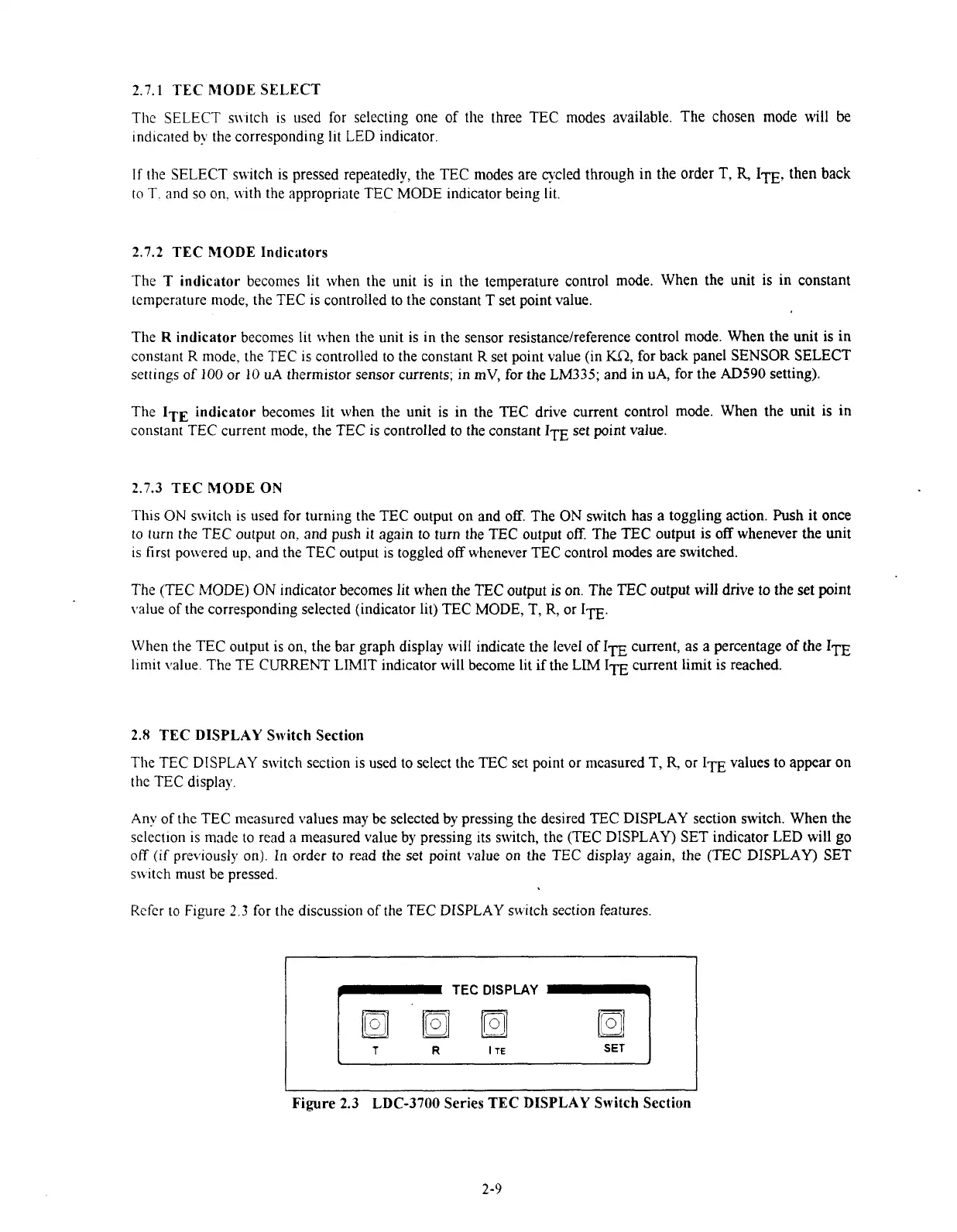
2.8
TEC DISPLAY Switch Section
The TEC DISPLAY switch section is used to select the TEC set point or measured T,
R
or
I=
values to appear on
the TEC display.
Any of the TEC measured values may be selected by pressing the desired TEC DISPLAY section switch. When the
select~on is made to read a measured value by pressing its switch, the
(TEC
DISPLAY) SET indicator LED will go
off
(if
previously on). In order to read the set point value on the TEC display again, the
(TEC
DISPLAY) SET
sn~tch must
be
pressed.
Refer to Figure
2.3
for the discussion of the TEC DISPLAY switch section features.
f
TEC
DISPLAY
T
R
I
TE
SET
Figure
2.3
LDC-3700 Series
TEC
DISPLAY Switch Section
Artisan Technology Group - Quality Instrumentation ... Guaranteed | (888) 88-SOURCE | www.artisantg.com

 Loading...
