5.3
LASER
Board
Theory
of
Operation
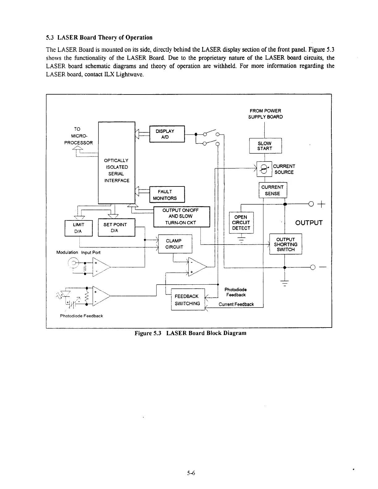
The
LASER Board is mounted on its side, directly behind the
LASER
display section of
the
front
panel.
Figure
5.3
shows the functionality of the
LASER
Board. Due to the proprietary nature of
the
LASER
board circuits, the
LASER board schematic diagrams and theory of operation are
withheld.
For more information regarding the
LASER board, contact
ILX
Lightwave.
PROCESSOR
id
OPTICALLY
ISOLATED
SERIAL
INTERFACE
FAULT
MONITORS
OUTPUT
ONIOFF
AND SLOW
SET POINT
TURN-ON CKT
L-
CIRCUIT
FROM POWER
SUPPLY
BOARD
CURRENT
SOURCE
SENSE
CIRCUIT
DETECT
-
SWITCHING Current Feedback
Photodiode
Feedback
Photodiode Feedback
OUTPUT
SHORTING
SWITCH
Figure
5.3
LASER
Board
Block
Diagram
Artisan Technology Group - Quality Instrumentation ... Guaranteed | (888) 88-SOURCE | www.artisantg.com

 Loading...
