The (LASER DISPLAY) SET mode is determined by the LASER MODE selection.
If
it is desired to change a set
point for a mode other than the present LASER MODE selection, it is first necessary to select the desired LASER
MODE
(see Section 2.11.2).
When (LASER MODE) P is selected. and the (LASER DISPLAY) SET switch is pressed, the (LASER DISPLAY)
IpD
or PPD indicator will become lit. If the
CAL
PD value is zero, the IpD set point will be displayed, since the unit
is in constant photodiode current mode. If the
CAL
PD value is non-zero, the PpD set point will be displayed, since
the unit is in constant photodiode power mode.
2.12.2
LASER DISPLAY Indicators and Switches
The
I
indicator becomes lit when laser drive current is displayed. When the
I
switch is pressed, the display will
show measured laser current in n1A. If the (LASER DISPLAY) SET switch is then pressed (and I mode is selected
in the
LASER
MODE section), the display will show the laser current set point value in mA.
The
IPD
indicator becomes lit when monitor photodiode current is displayed. When the IpD switch is pressed, the
LASER display will show measured PD monitor current in uA.
If
the
(LASER
DISPLAY) SET switch is then
pressed (and
P
mode is selected in the LASER MODE section, and the
CAL
PD value is zero), the display will
show the monitor PD current set point value, in uA.
The
PI,,,
mdicator becomes lit when the user-programmed optical power is displayed. When the PpD switch is
pressed. the LASER display will show measured optical power in mW, as it relates to the monitor photodiode
current (see Section
2.13.5).
If the (LASER DISPLAY) SET switch is then pressed (and
I
or
IHBW
mode is selected
in the LASER MODE section and the
CAL
PD value is non-zero), the display will show the optical power set point
value. In
mW.
If
the CAL PD parameter value is zero, and the P mode is selected in the LASER MODE section, the unit will
operate ~n constant IpD mode, and the PpD display will indcate
"-.-"
when the PpD display is selected.
The (LASER DISPLAY)
SET
indicator becomes lit when the display is showing the SET (set point) value. The
(LASER DISPLAY) SET indicator goes off when the display is showing a measured value.
2.13
LASER
PAR4hIETER
Scction
The
LASER
si~~tch (~n the
ADJUST
section) must be engaged (indicator lit) to adjust the LASER PARAMETER
\
alues.
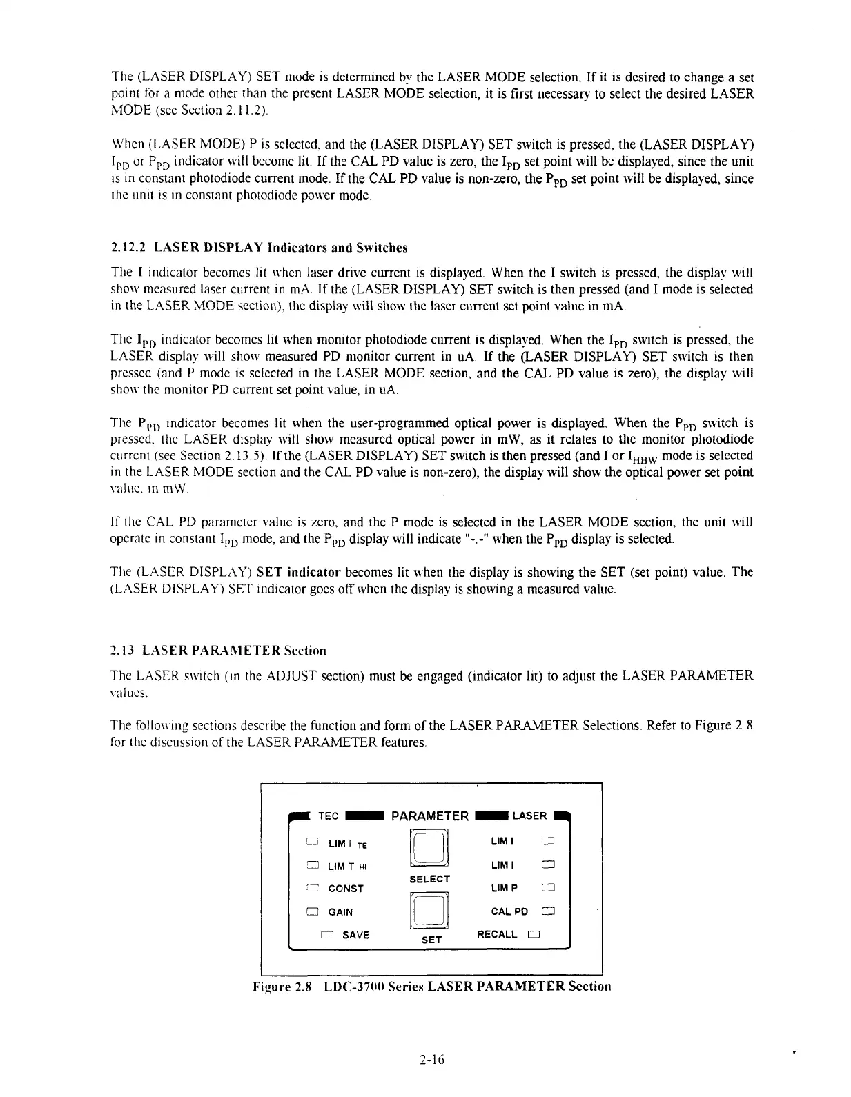
The follov
ing
sections describe the function and form of the LASER PARAMETER Selections. Refer to Figure
2.8
for
the discuision of the LASER PARAMETER features
TEC
PARAMETER
LASER
SELECT
!
>AVt
SET
ncw
3
CONST
LIM
P
O
O
GAIN CALPD
C3
C
-""
---\LL
0
Figure
2.8
LDC-3700 Series LASER PARAMETER Section
2-16
Artisan Technology Group - Quality Instrumentation ... Guaranteed | (888) 88-SOURCE | www.artisantg.com

 Loading...
