2.13.5
CAL PD
Thc
CAL
PD
indicator becomes lit when the monitor photodiode responsivity parameter is displayed. The
responsi\ih is displayed in uAlmW. The responsivity is entered
by
the user (in uAlmW) after performing the
folio\\-ing
measurements:
1
Measure (with a calibrated detector) the output power of the device.
2.
Measure the corresponding photodiode current.
3.
Calculate the responsivih by dividing the optical power into the corresponding photodiode current.
This value is normally used to convert between optical power and optical current
of
the monitor photodiode. This
parameter is used to convert between
IpD
and
PpD
values. However, when the CAL
PD
value is set to zero, the unit
may be operated in constant
IpD
mode.
When the
CAL
PD
value is zero, the LASER output will be controlled to the
IpD
set point value, and the
PpD
display \\.ill indicate
"-.-"
when it
IS
selected.
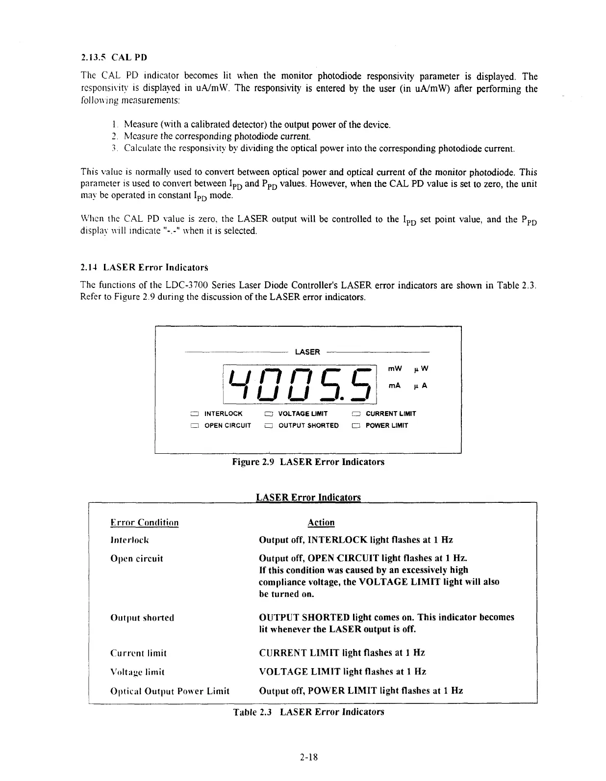
2.14
LASER Error Indicators
The functions of the
LDC-3700
Series Laser Diode Controller's LASER error indicators are shown in Table
2.3.
Refer
to
Figure
2.9
during the discussion
of
the LASER error indicators.
I
LASER
3
INTERLOCK
O
VOLTAGE LIMIT
c:
CURRENT LIMIT
C1
OPEN CIRCUIT
iZ
OUTPUT SHORTED
IT
POWER
LlMlT
Figure 2.9 LASER Error Indicators
LASER Error Indicators
Error Condition Action
Interlock
Output off, INTERLOCK light flashes at
1
Hz
Open circuit
Output shorted
Current
limit
Output off, OPEN CIRCUIT light flashes at
1
Hz.
If this condition was caused
by
an excessively high
compliance voltage, the VOLTAGE LIMIT light will also
be turned on.
OUTPUT SHORTED light comes
on.
This indicator becomes
lit whenever the LASER output is off.
CURRENT LIMIT light flashes at
1
Hz
I
Voltilgc limit
VOLTAGE LIMIT light flashes at
1
Hz
1
0ptir;d Outl~ut Power Limit
Output off, POWER LIMIT light flashes at
1
Hz
Table
2.3
LASER Error Indicators
2-18
Artisan Technology Group - Quality Instrumentation ... Guaranteed | (888) 88-SOURCE | www.artisantg.com

 Loading...
