43
INSTALLER
USERMAINTENANCE TECHNICIAN
TECHNICAL DATA
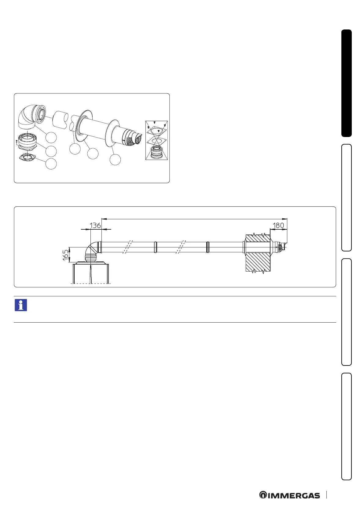
Horizontal intake/exhaust assembly kits Ø 80/125 (Fig. 22)
To install the kit Ø 80/125 one must use the anged adapter kit (pos. 2, Fig. 22).
1. Install the anged adaptor (2) on the central hole of the appliance, positioning gasket (1) with the circular projections downwards in
contact with the appliance ange, and tighten using the screws contained in the kit.
2. Engage the bend (3) with the male side (smooth) to the end stop on the adapter (2).
3. Fit the Ø 80/125 (4) concentric terminal pipe with the male side (smooth) to the female side of the bend (3) (with lip seals) up to the end
stop, making sure that the internal (5) and external wall sealing plates (6) have been tted; this will ensure sealing and joining of the
elements making up the kit.
C
13
1
2
3
4
5
6
22
e adapter kit includes (Fig. 22):
N° 1 Gas ke t (1)
N°1 Adapter Ø 80/125 (2)
e Ø 80/125 kit includes (Fig. 22):
N°1 Concentric bend Ø 80/125 at 87° (3)
N°1 Int./exhaust concentric terminal Ø 80/125 (4)
N°1 Internal wall sealing plate (5)
N°1 External wall sealing plate (6)
e remaining kit components must not be used
Extensions for horizontal kit Ø 80/125 (L = maximum length) (Fig. 23).
C
13
23
To calculate the length of the ue, simply add, for each component you intend to use, the corresponding value indicated in the
column "Length equivalent to m of pipe" in the table in par. 1.14, and check that the resulting sum is equal to or less than the
maximum length indicated in par. 1.15.
 Loading...


