52
INSTALLERUSERMAINTENANCE TECHNICIANTECHNICAL DATA
Concentric kit assembly in C
10
type conguration (Fig.37)
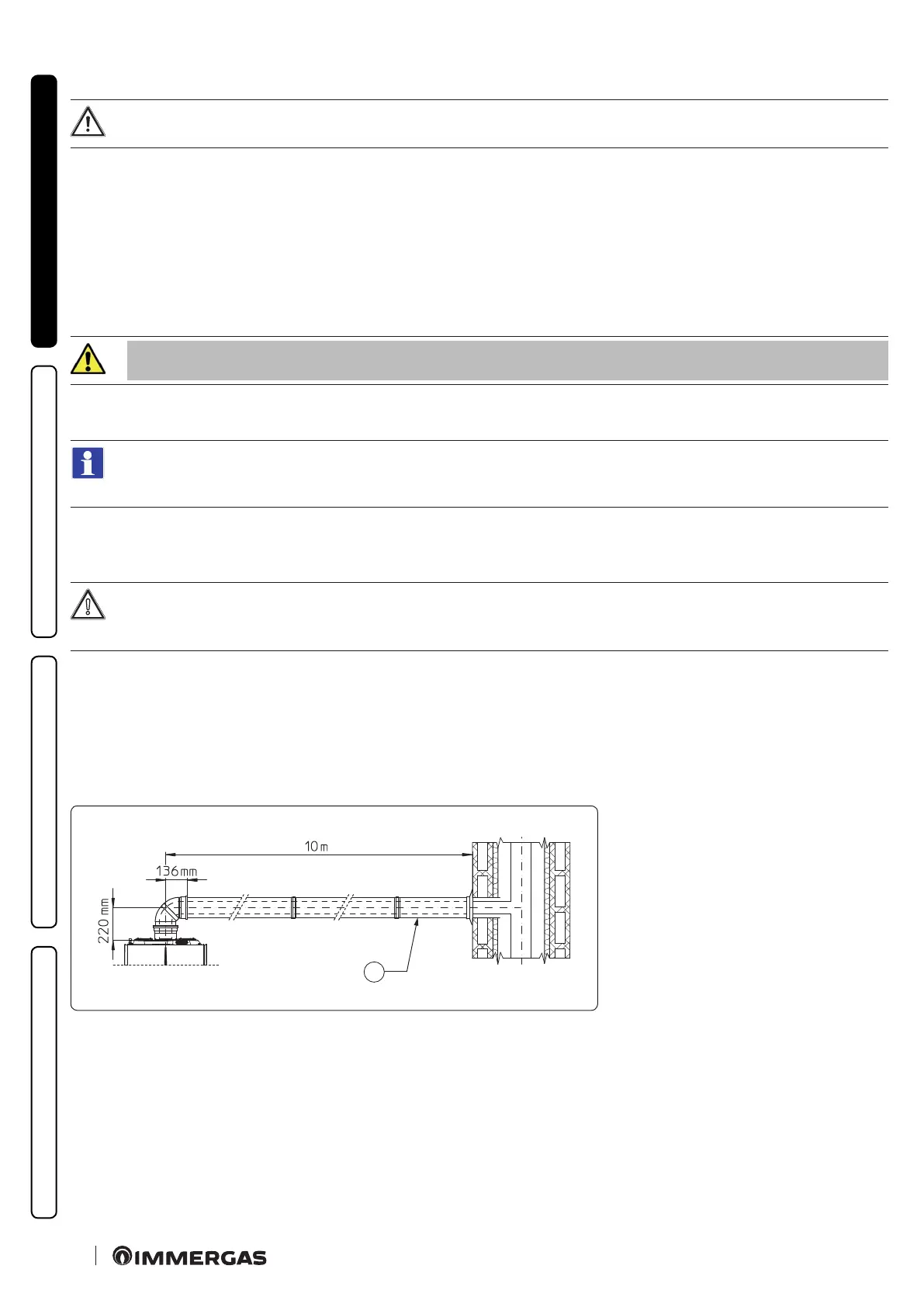
To aid in the removal of possible condensate forming in the exhaust pipe, tilt the pipes towards the appliance with a minimum
slope of 5% (Fig.36).
1. Position the anged adaptor (14) interposing the concentric gasket (15) on the appliance, tting it with the screws (13).
2.
Victrix Tera V2 24 PLUS EU
Maintain the counterweight supplied as per standard (h. 3,5 mm) mounted on the large ap of the valve and discard the one supplied
bulk (h. 6,5 mm) inside the kit (Fig. 34).
Victrix Tera V2 35 PLUS EU
Replace the counterweight supplied as per standard (h. 3,5 mm) mounted on the large ap of the valve with the counterweight sup-
plied bulk (h. 6,5 mm) inside the kit. Discard the counterweight (h. 3,5 mm).
3. Insert the non-return valve kit on ue gas Ø80 in the anged adapter, taking care to remove the spacer Ø 80 th. 5 mm.
Make sure to ll the ue gas non-return valve siphon with water (Fig. 34):
4. Fit the Ø 125 extension in the anged adapter.
5. Insert the Ø 80/125 bend on the non-return valve.
To calculate the length of the ue, simply add, for each component you intend to use, the corresponding value indicated in the
column "Length equivalent to m of pipe" in the table in par. 1.14, and check that the resulting sum is equal to or less than the
maximum length indicated in par. 1.15.
6. Calculate the distances between the bend and the connection to the collective ue and the sha.
7. Adapt the extension (10), calculating that the inner pipe of the concentric kit must t as far as it will go into the collective ue. e out-
er pipe must engage up to the door.
Before mounting it, ensure that the gaskets are in the correct position.
In the event component lubrication (already carried out by the manufacturer) is not sucient, remove the residual lubricant
using a dry cloth, then to ease tting coat the parts with common or industrial talc.
8. Mount the cover (A) complete with adaptor (1) and caps (6) on the wall.
9. Assemble the ue to the collective ue exhaust system.
10. Set parameter P8 = 1.
11. Set the fan speed according to the table (par. 3.8).
12. Calibrate the CO
2
at maximum and minimum output (Ref. Par. 4.2).
Once all components have been assembled properly, the exhaust ue gas will be expelled in the collective ue, the combustion air for
normal appliance operation will be aspirated directly by the sha (Fig. 33).
C
10
C
36
Key (Fig. 36):
C - Minimum slope 5%
 Loading...


