EasyManuals Logo

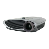
InFocus LP500 Service Guide

InFocus LP500
120 pages
To Next Page IconTo Next Page
To Previous Page IconTo Previous Page
Page #100 background imageLoading...
Page #100 background image
LP500 Series Service Manual 100
Block Diagram
Deinter-
lacer
Analog to
Digital
Converter
Digital
Receiver
D-24b RGB
Digital Video Bus
TI Formatter
Bias setting ICs
Color wheel
motor control
Frame formatting
3V
Rear IR receiver
0V
Gnd
Vcc 5V
12V
Lamp
Lamp HV
Safety switch cable
Reset
PixelWorks
ASIC
Image processing
System management
8 Mb Flash
Sync
M1 digital or
analog connector
Lamp blower
Lamp fan
Front fan
Grnd
Grnd
RGB
Thermistors
USB
Receiver
Power Supply / Ballast
Power supply fan
Gnd
+3.3V
Top IR receiver
IR
ECA
5V
3.3V
3.3V
N/A
Grnd
- 8V to - 9.2V
Lamp Lit
3V lit
0V not lit
Gnd
Lamp
door
interlock
switch
Thermal
switch
on lamp
housing
I
2
C
Audio mixer
Amplifier Speaker
Fan fail
Fan fail
Fan fail
Fan fail
Video
Decoder
Expansion
Module
Keypad
controller
Fan
control
DMD
Composite
SVideo
Color
wheel
Keypad
Audio In
RS232
Lamp enable
Lamp
enable
5V lit
Power Supply / Controller connector
See Controller Voltages for specific information about voltages (page 99)

Table of Contents

Other manuals for InFocus LP500

Questions and Answers:

Question and Answer IconNeed help?

Do you have a question about the InFocus LP500 and is the answer not in the manual?

InFocus LP500 Specifications

General IconGeneral
BrandInFocus
ModelLP500
CategoryProjector
LanguageEnglish

Related product manuals