LP500 Series Service Manual 46
Remove and replace the chassis
The metal chassis (330-0702-xx) provides the necessary rigidity for the projector’s internal components,
yet it adds very little to the overall weight.
1 Remove the controller ECA (see page 30).
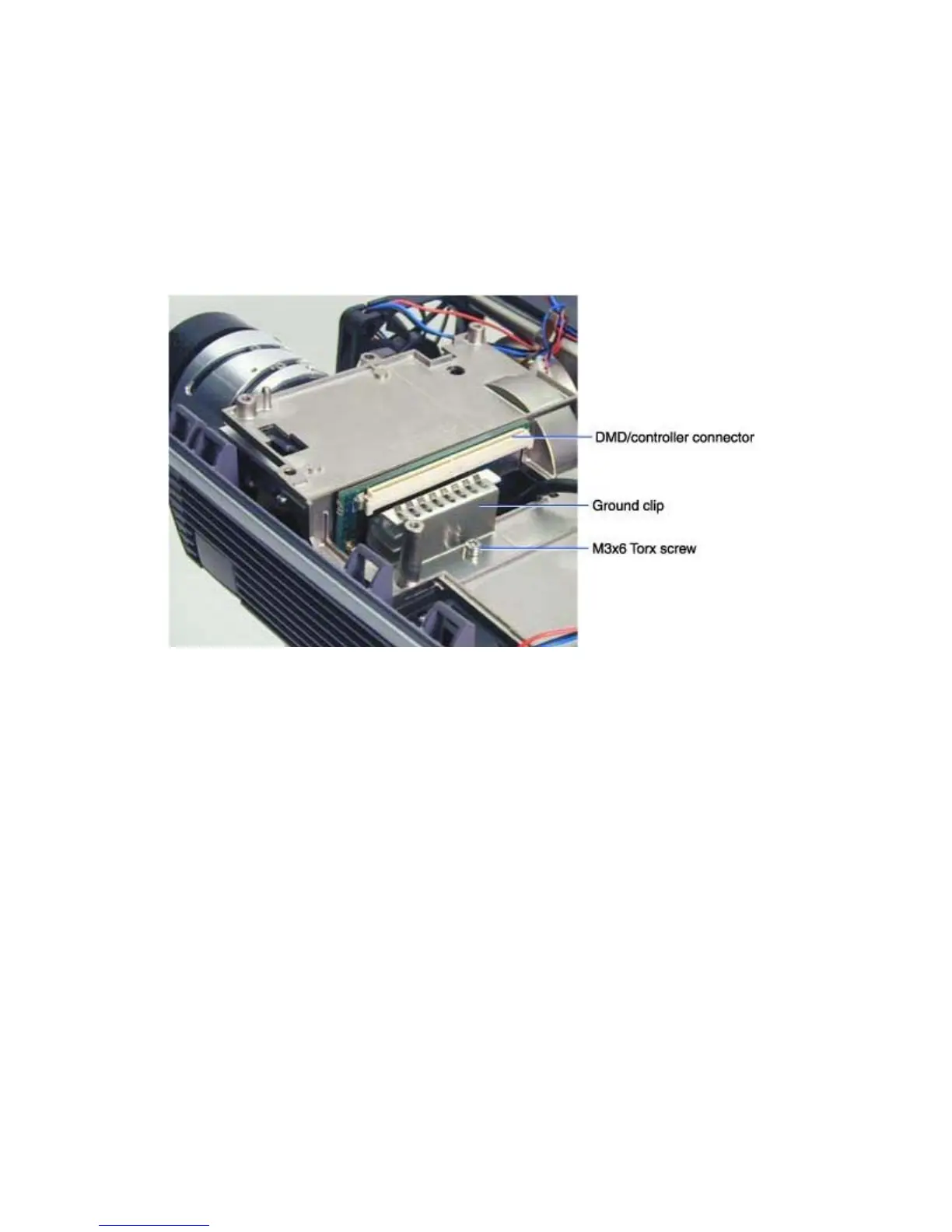
2 Remove the M3x6 Torx screw that fastens the ground clip (320-0357-xx) to the chassis adjacent
to the DMD/controller connector. Then lift the ground clip off of the chassis. Set the ground clip
aside. You need to fasten it to the new chassis.
3 Remove the Chassis and power supply (see page 39)
4 Place the chassis on the work space and remove the following parts:
5 Power supply fan and interlock switch cable (see page 55)
6 Power supply(see page 51)
7 Rear bezel (includes diode gap pads, heat sink and power supply insulator) (see page 43)
8 You are left with the bare chassis.
Assembly Notes
♦ Install the parts in the reverse order. You can install the ground clip before you install the chassis and
parts in the bottom case.
♦ Torque the M3x6 Torx screw on the ground clip to 6 in/lbs (.68 Nm).