trapulsPac - User Guide
Chapter 3 – Reference
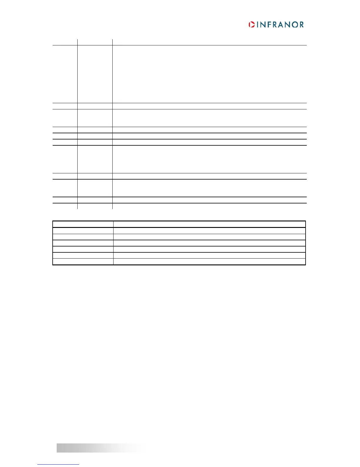
Bit Name Description
0-1 SELECT_INP Inputs Selection:
0 Inputs from Encoder connector (differential line driver inputs)
A+/A- -> A or PULSE
B+/B- -> B or DIR
1 Inputs from I/O connector (logic opto-coupler inputs)
IN5 -> A or PULSE
IN3 -> B or DIR
2 Inputs from Hall Effect Sensor (Encoder connector)
Hall U -> A or PULSE
Hall V -> B or DIR
2 Reserved. Must be 0.
3 CNT_MODE Inputs Count Mode:
0 Quadrature (A/B) inputs
1 Pulse/Dir inputs
4 PULSE_POL PULSE or A polarity
5 DIR_POL DIR or B polarity
6 Reserved. Must be 0.
7 PULSE_DBL Pulse Count Mode (only for PULSE/DIR input)
0 Simple count. Count on rising edge of PULSE
Motor Speed (rpm)=60 * Pulse_Frequency / User position scaling (0x6093-2)
1 Double count. Count on rising edge and falling edge of PULSE
Motor Speed (rpm)=120 * Pulse_Frequency / User position scaling (0x6093-2)
8 COUNT_ENA Count Enable
11 FILTER_ENA Low pass filter:
0 Filter disabled
1 Filter enabled (see 0x3683 for the cut-off frequency setting)
others Reserved. Must be 0.
Sub Index 4
Description PULSE_CNT timeout
Data Type Unsigned16
Access rw
PDO Mapping No
Unit ms
Default value 10
This parameter defines the timeout after the last pulse the signal PULSE_DIR will be reset.
 Loading...

