User Manual for the Thermographic System VarioCAM
®
high resolution
8. Operation
User Manual © InfraTec GmbH 2013 59
Menu item "Alarm.." permits to define temperature thresholds. Should one of these threshold levels be
reached, the alarm function selected from "Action" will be activated.
Should ROIs (see Chapter 8.2.4, Spot Editor*, page 28) have been generated in the thermal image, the alarm
function will exclusively apply to this area.
Should no ROI have been generated in the thermal image, the alarm function will apply to the entire thermal
image.
Two alarm thresholds can be defined.
In boxes "Alarm 1/2", values exceeding "U" or falling short of "D" or reaching the mean value "M" for
the temperature as set in "Threshold 1/2" can be determined.
The respective temperature threshold value relating to the respective box "Alarm 1/2" is entered into
boxes "Threshold 1/2".
In box "Action" it can be decided which action shall be taken in the case of alarm:
■ "S" Save – saves a thermal image
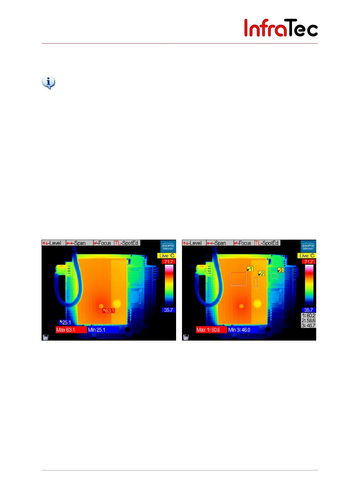
■ "V" Visual display – displays the respective status (see Fig. 124 and Fig. 125)
■ "X" External – transmits the alarm value in Kelvin via RS232* from the VarioCAM
®
hr
■ "A" Acoustic alarm
Fig. 125 Displayed visual alarm when exceeding
and falling short (U/D) of the thresholds
in the entire thermal image
Fig. 126 Displayed visual alarm by exceeding
the threshold in ROI 1 and by falling
short of the threshold in ROI 3