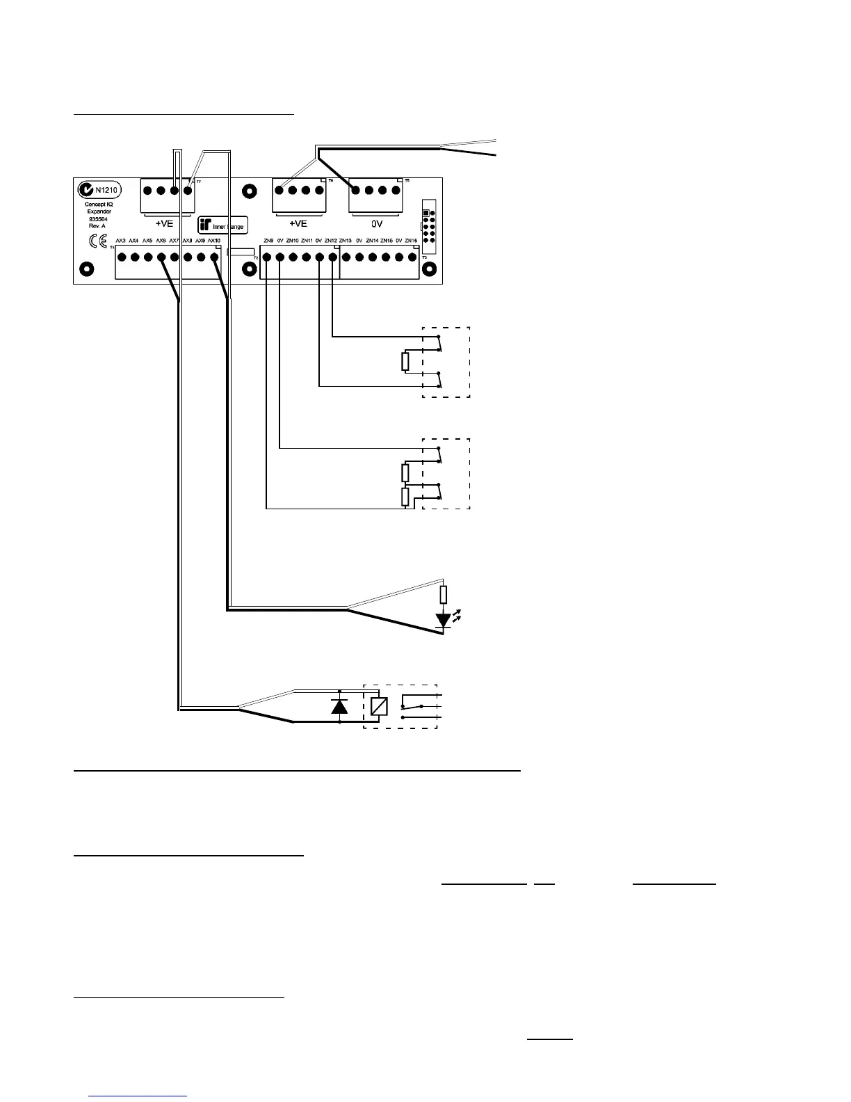
Section 1. Installation. CONCEPT IQ. Installation & Programming Manual.p12
T2 and T3. Zone Input connections.
Single End-of-Line.
Dual End-of-Line.
T5 & T6. “+VE” and “0V”.
Detector Power connections.
12V Supply for Detectors.
Total combined current sourced from
“DET+” and “LAN+” on the Control
Module, and “+ve” on the Expander Card
must not exceed 600 milliAmps.
Minimum Cable spec: 14/0.2
Tamp.
Alarm
Detector
C
NC
C
NC
EOL Res.
3k3 Typ.
Tamp.
Alarm
Detector
C
NC
C
NC
EOL Res.
3k3 Typ.
6k8 Typ.
T4. Auxiliary Output connections.
995504 Only.
LED wiring.
(Note. Dropping Resistor can be any
value in the range of 1k to around 1k5.
e.g. 2 x 3k3 Resistors in parallel)
Relay wiring.
Relay coil voltage: 12V DC
Fit reverse diode across coil.
e.g. 1N4001 - 1N4004.
1k min.
Relay
NC
O
NO
EXPANDER CARD WIRING DIAGRAMS.
IMPORTANT NOTE. AUXILIARY POWER:
Total combined current sourced from “DET+” and “LAN+” on the Control Module, and “+ve” on the Expander Card
must not exceed 600 milliAmps.
If additional current is required, a separate, external Power Supply and backup battery must be used to provide power to
the required Auxiliary devices and/or Detectors.
e.g. 994051 2A Power Supply.
994055 Short-form Power Supply Board + 560001 Plug pack (For 1A PS), or 560004 In-line transformer (For 2A PS)
When a separate Power Supply is used:
1) The Power Supply must be installed close to the Control Module, and the 0V (or “-VE”) supply connections of the
Power Supply and the Control Module must be connected together using a heavy guage wire. (14/0.20 minimum)
2) The “+ve” supply connections of any system Module (“DET+”, “LAN+” or “+VE”) must not be connected to +ve of the
separate Power Supply.
NOTE: ZONE INPUT CONNECTIONS. “NORMALLY OPEN” ALARM CONTACTS.
Normally Open Alarm Contacts (e.g. As often found on Smoke Detectors) are wired in the same manner as Normally
Closed contacts. When programming the Zone Input, Option 8 (“Normally Open”) in the “Zone Options” must be selected.
(Addresses 752 [Zone 1] to 767 [Zone 16] )

 Loading...
