CONCEPT IQ. Installation & Programming Manual.
Install
p13
DTMF Card. 995505
© 2001. Inner Range Pty. Ltd. Part No: 635505
INSTALLATION.
- Remove the screw on the top edge of the Control Module PCB next to the STATUS Lamp.
- Fit the Brass PCB standoff in place of the screw.
- Plug the DTMF Card onto the box header JP10 on the Control Module (“DTMF PORT”).
- Secure the DTMF Card to the standoff using the screw removed from the Control Module.
- Program the required DTMF functions. See Installation & Programming Manual, Section 10: Communications.
DTMF Card Parts List
- DTMF Card.
- Installation Manual. (This document)
- 1 x 20mm Brass PCB standoff.
The DTMF Card connects directly to the Control Module DTMF Port to provide Telephone remote control.
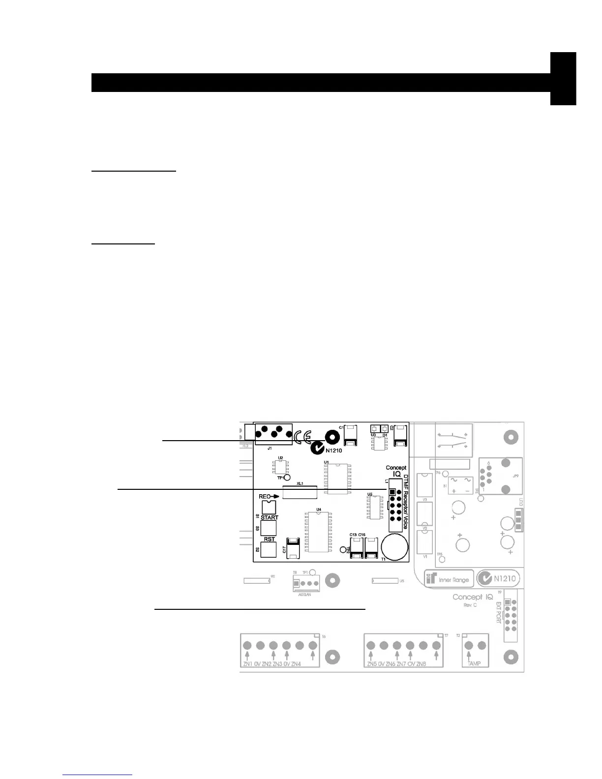
Location of Brass
PCB standoff.
JP10.
“DTMF PORT”.
Control Module.
DTMF Card. Version 1.00

 Loading...
