CONCEPT IQ. Installation & Programming Manual.
Install
p11
Expansion Card. 995503 / 995504
© 2001. Inner Range Pty. Ltd. Part No: 635504
Expansion Card Parts List
- Zone/Auxiliary Expansion Card.
- Installation Manual. (This document)
- Installation Kit containing:
- 3 x 20mm Brass PCB standoff.
- 1 x 20mm Threaded plastic PCB standoff.
- 1 x Pan Head M3x6mm screw.
- 2 x 6 Way plug-on screw terminals.
- 4 x 2 Way plug-on screw terminals.
- 10 x 3k3 End-of-line resistors. 8 x Zone Inputs, 2 x Spare. (orange-orange-black-brown-brown)
- 10 x 6k8 End-of-line resistors. 8 x Zone Inputs, 2 x Spare. (blue-grey-black-brown-brown)
The Expansion Card connects directly to the Control Module Expansion Port and is available in 2 Versions:
995503. Zone Expansion Card.
Provides 8 additional Zone Inputs and additional Detector power connections.
995504. Zone & Auxiliary Expansion Card.
Incorporates all Zone Expansion card features along with 8 additional low power open-collector Auxiliary Outputs and 4
additional +12V Auxiliary power outputs.
INSTALLATION.
- Remove all power to the Control Module. Remember to disconnect the Battery. See Note 1 below.
- Remove the 3 screws along the bottom edge of the Control Module PCB. (The screws adjacent to T4, T6 & T2)
- Fit the 3 Brass PCB standoffs in place of these 3 screws.
- Fit the Threaded plastic PCB standoff into the mounting hole on the Control Module PCB next to T8 (AUX LAN).
- Plug the Expander Card onto the box header T9 on the Control Module (“EXT PORT”).
- Secure the Expander Card to the 4 standoffs using the 3 screws removed from the Control Module and the additional
screw provided in the Installation kit.
- Connect the additional Zone Inputs and/or Auxiliary Outputs required.
- Reconnect the power and the Battery to the Control Module, then program the required Zones and Auxiliaries.
NOTES: 1) CAUTION: Shorting any of the pins on the Expansion Port connector whilst powered up, can result
in permanent damage to the Control Module and/or the Expansion Card.
2) Zone Doubling CANNOT BE USED on the system when an Expander Card is fitted.
See next page for Zone Input & Auxiliary Output wiring.
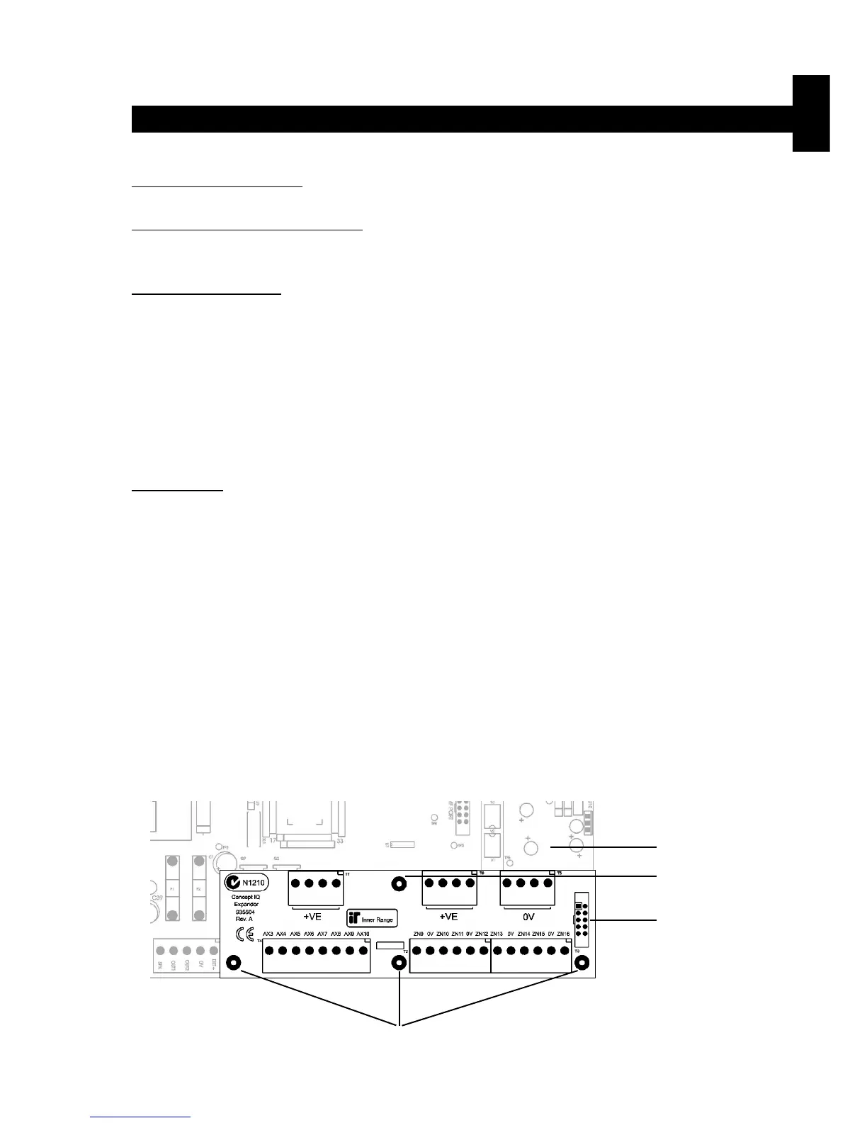
Location of Brass
PCB standoffs
Control Module.
Location of Threaded
plastic PCB standoff.
Expansion Port.
T9. “EXT PORT”.
Expansion Cards. Version 1.00
 Loading...

