Section 1. Installation. CONCEPT IQ. Installation & Programming Manual.p10
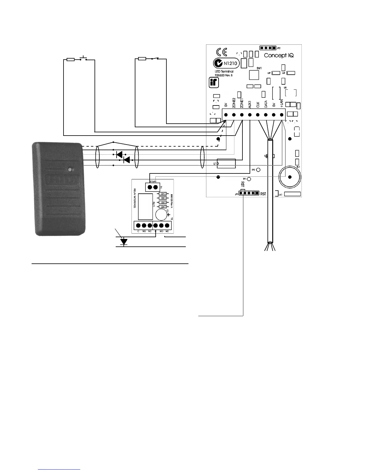
LAN connections to
the Control Module
T4 connector.
4 Core
Security Cable
recommended.
(14/0.2)
ADDRESSING & COMMISSIONING (Read “LAN connection” first)
1. Enable Terminal Configuration Mode.
Method 1: -Remove power from the Terminal.
-Hold down the <NEXT> and <HOME> keys.
-Re-apply power to the Terminal.
-Release the <NEXT> and <HOME> keys.
Method 2: -Hold down the <NEXT> and <HOME> keys.
-Short the “RST” (Reset) link on the rear of the Terminal.
-Release the <NEXT> and <HOME> keys.
2. Note the current Address setting. The current Address of the Terminal will be displayed via the Zone 1 to 4 Lamps.
The Zone Lamp number that corresponds to the current Address will flash.
3. Select the new Terminal Address number.
-Press the key that corresponds to the required Address (1 to 4) within 10 seconds, then press <ENTER>.
4. Note the current Door Alarm enable status.
After the Terminal Address has been entered as per Step 3, the display will now show the current Door Alarm enable
status: 0 = Disabled (Default)
1 = Enabled
5. Enable / Disable Door Alarm.
If an Enhanced Terminal is required to generate a Door Alarm for Door Forced or Door Held conditions, then “Door
Alarm” must be enabled for that Terminal.
-To Enable or Disable, select the option required (0 or 1) within 10 seconds, then press <ENTER>.
-When the <ENTER> key is pressed, the Enhanced Terminal will now exit Terminal Configuration Mode.
6. Initialize the LAN. If a new Terminal is added to an existing system, once the Terminal is configured and connected
to the system LAN, the LAN must be initialized by Removing and Re-applying power to the Control Module.
Remember to disconnect the battery also when removing power.
7. Area Assignment. Enhanced Terminals must be configured for Single Area Mode (Address 961), and an “Associated
Area” must be defined for each Terminal (Addresses 952 to 955).
8. Door Un-lock time. The system has a default Door Un-lock time of 5 seconds. If a different time is required, this value
can be edited at Address 872.
Request to Exit (REX) button
(Normally Open)
EOL Res.
6k8
Door Reed Switch
(Normally Closed)
EOL Res.
6k8
Shield
0V Black
D0 Green
D1 White
+ Red
To Lock -
Strike +
- From Lock
+ Power Supply
*
1A DPDT Relay
Board. 995085
* Pwr to Lock: Use NC
Pwr to Unlock: Use NO
4 Core
Security Cable
recommended.
(14/0.2)
Shielded RS232 Data cable.
Fit reverse
Diode across
Lock coil.
 Loading...

