Section 2. Intro. Version 1.01 p7CONCEPT IQ. Installation & Programming Manual.
Intro
3.4 MODE “02”. DEFAULTING THE CONTROL MODULE.
Defaulting the Control Module allows the Installer to clear any current system programming from the Control Module
and select a factory default database to simplify the programming task.
The Default Database options can be divided into 3 main options:
Option 0: The Control Module memory is completely cleared with the exception of the Installer and Master
User Codes.
Options 1 to 16: The Control Module memory is defaulted to the Factory settings shown in the table on the following
page AND the number of Zones specified by the Option selected, are programmed into Area 1.
Option 49: The Master Code is defaulted to the Factory setting and all other programming is left intact.
CAUTION: Defaulting the Control Module will erase all current programming stored in the memory before
implementing any Factory default settings. (With the exception of Default Option 49)
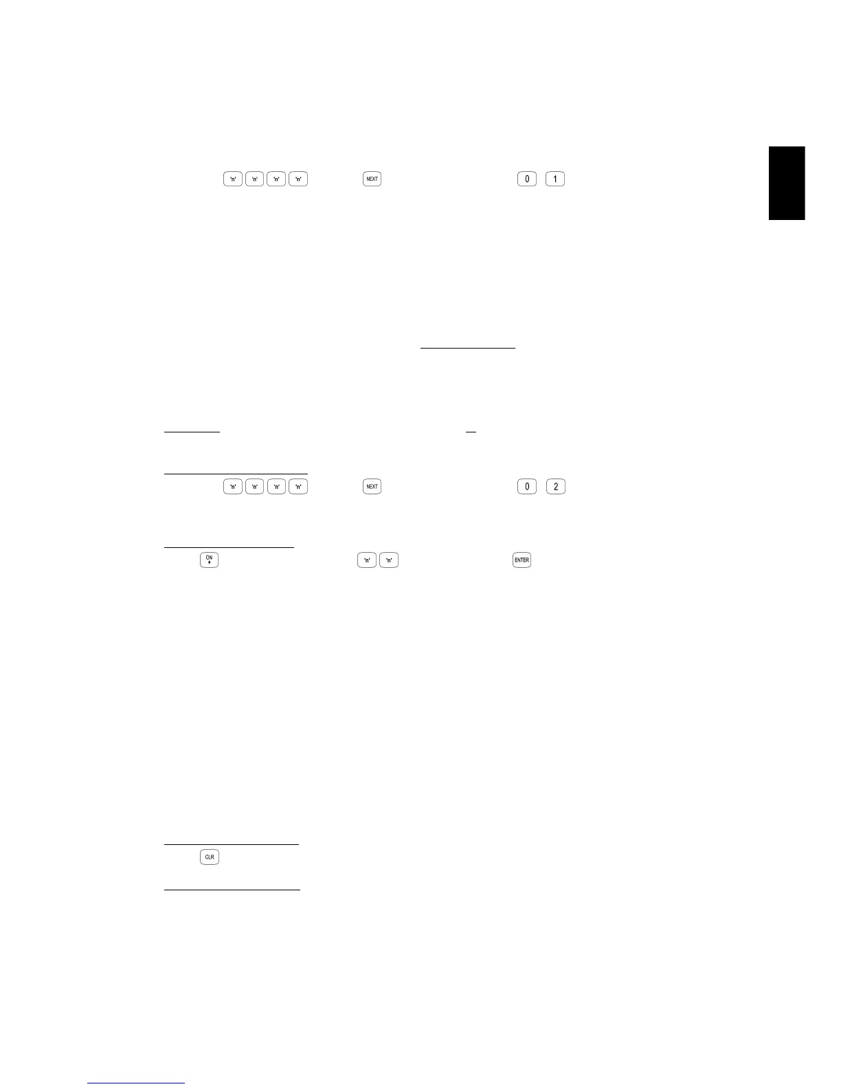
Select the Defaulting Mode:
Enter PIN; ... , then , then the Mode number; ,
The <HOME>, <FAULT> and <PWR> Lamps on the LED Terminal will flash simultaneously.
Select the Default Option
Press , then the Default Option (1 or 2 digits), then
DEFAULT OPTIONS:
0: Database is completely cleared except for Installer & Master Codes.
1: Database is defaulted to Factory Default settings AND 1 Zone is programmed into the system.
2: Database is defaulted to Factory Default settings AND 2 Zones are programmed into the system.
3 to 15: Database is defaulted to Factory Default settings AND the specified number of Zones are programmed
into the system. i.e. 3 Zones to 15 Zones.
16: Database is defaulted to Factory Default settings AND 16 Zones are programmed into the system.
49: Master Code Default. Only the Master code is reset to the factory default. All other programming remains
unchanged.
NOTES:
1) The product is dispatched from the factory Defaulted with Option 8 (Factory Default settings and 8 Zones)
2) In Default Options 1 to 16, the Zones programmed into the system are assigned to Area 1.
3) If Default options 9 to 16 are used, and Zones 9 to 16 are added using Zone Doubling (i.e. Not via an
Expander card), the “End-of-Line Resistor value” (Address 786) must be set to Type 14 - Zone Doubling.
Exit from Defaulting Mode
Press to exit.
Reset the Control Module:
Disconnect the AC Input and the Battery from the Control Module, then re-connect.
This mode allows the Installer to program all of the system data and options.
To Select Programming Mode:
Enter PIN; ... , then , then the Mode number; , .
See “Basic Programming Techniques” and “Types of Data” for more details of Programming Mode.
3.3 MODE “01”. PROGRAMMING MODE.
HARDWARE DEFAULT PROCEDURE.
The system can also be set to the Factory Default settings (Same as Default Option 8) via a hardware procedure.
- Disconnect the battery and remove power from the Control Module.
- Place a short circuit across Pins 2 & 3 of JP8 on the Control Module.
- Re-apply power to the Control Module and reconnect the battery.
- Remove the short circuit on JP8.