Section 2. Intro. Version 1.01 p9CONCEPT IQ. Installation & Programming Manual.
Intro
Terminal Programming allows the Installer to define which Area is to be associated with the LED Terminal.
NOTE: This Mode is only available if the Terminal is programmed for Multi-Area mode. (Address 960. Option 1
must be Selected)
Select the Terminal Programming Mode:
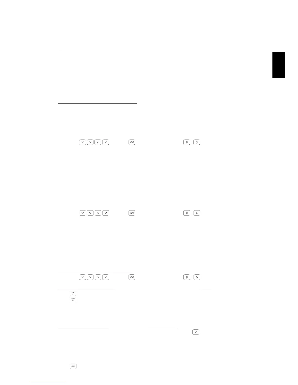
Enter PIN; ... , then , then the Mode number; ,
Select the Terminal Area Mode: (Not relevant to Enhanced Terminals which cannot be set to Multi-Area)
Press to Set the current Terminal to Single Area Mode.
Press to Set the current Terminal to Multi Area Mode.
Note that this operation will Edit the relevant option in Address 961, Terminal Area Mode.
When Single Area Mode is selected, the default “Associated Area” is Area 1 (General Area)
Select the Associated Area: (Single Area Mode must be selected in the previous step)
To select the Associated Area for the current Terminal, press the number (1 to 4) of the Area.
The Area selected will be displayed on the Area Lamps.
A long beep will sound if the terminal is not in Single Area Mode or the wrong key is pressed.
Note that this operation will Edit the data in the relevant Addresses 952 to 955, Terminal 1 to 4 Associated Area.
Press to exit Terminal Programming Mode.
3.6 MODE “03”. IMPORT DATA FROM THE PROGRAMMING KEY.
3.7 MODE “04”. EXPORT DATA TO THE PROGRAMMING KEY.
The Programming Key.
The Concept IQ Programming Key is a portable non-volatile memory device housed in a convenient “key tag”.
The Programming Key allows system programming to be uploaded from the Control Module or downloaded to the
Control Module by simply inserting the Programming Key into Serial Port 0 and performing a simple key sequence
on the LED Terminal.
A built-in Lamp on the Programming Key visually indicates when data transmission is active.
Importing Data from the Programming Key.
This Mode allows the Installer to copy the programming contents of the Programming Key into the Control Module.
IMPORTANT NOTE: The new data will override the existing contents of the Control Module memory.
Connect the Programming Key to Serial Port 0 on the Control Module.
Select the Import Data Mode:
Enter PIN; ... , then , then the Mode number; , .
The Lamp on the Programming Key will flash slowly to indicate data is being copied.
The Terminal beeper will sound 3 short beeps if the operation was successful, or 1 long beep if unsuccessful.
This Mode allows the Installer to copy the programming contents of the Control Module into the Programming Key.
IMPORTANT NOTE: The Control Module data will override the existing contents of the Programming Key.
Connect the Programming Key to Serial Port 0 on the Control Module.
Select the Export Data Mode:
Enter PIN; ... , then , then the Mode number; , .
The Lamp on the Programming Key will flash quickly to indicate data is being copied.
The Terminal beeper will sound 3 short beeps if the operation was successful, or 1 long beep if unsuccessful.
3.8 MODE “05”. TERMINAL AREA PROGRAMMING.

 Loading...
