p2 Section 7. System I/Ps. Version 1.02 CONCEPT IQ. Installation & Programming Manual.
SYSTEM INPUT MAPPING AND FUNCTIONAL DESCRIPTION
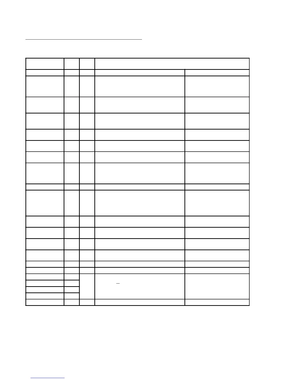
System Inputs are mapped to the Input Numbers shown in the following table.
NOTES:
1) If the Siren output is not used, or a High impedance device is connected (e.g. Piezo siren), a 6k8 resistor must be
installed across the Siren output to prevent the Siren Monitor Alarm from being activated.
2) Period specified by Telecommunications authority requirements.
3) Siren and Dialer operations for Keypad System Input alarms (Medical, Panic, Duress and Fire ) are programmed in
the “Emergency Options” programming. (Address 869)
ALARM INPUT
No.
Zone
Lamp
DESCRIPTION
Goes Into Alarm when: Restores when:
AC Fail 101 1 The AC mains has been absent for more than the
specified time period (AC Fail Delay).
When the input is in alarm the AC indicator on
theTerminal will flash.
The AC mains is restored.
Low Battery 102 2 The battery voltage falls below 11.2V during Battery Test
or while AC supply is not present. (Battery voltage is
too low to provide backup power if AC fails.)
The battery voltage is restored to above
11.2V.
Cabinet Tamper 103 3 The Control Panel cabinet cover is removed or the
cabinet is removed from it's mounting surface, causing
the Tamper Input to go unsealed.
The Tamper Input is sealed.
Siren Monitor Alarm 104 4 The Siren speaker is disconnected from the Control
Panel. *1
The input will restore when the
connection is restored.
PWR Fuse fail 105 5 Power fuse has blown. (Due to Short circuit or over-
current condition.)
The fuse has been replaced.
Battery Fuse fail 106 6 Battery fuse has blown. (Due to Short circuit or over-
current condition.)
The fuse has been replaced.
Comms Fail 107 7 System failed to report.
Attempts to dial out on both primary and backup
telephone numbers have failed. The system will try to
dial again after waiting 30 minutes. *2
On the next successful dial.
System Reset 108 8 The Control panel has been reset.
Keypad Lockout 109 9 The System has registered 5 incorrect PIN code
attempts in a row.
The system will not allow keypad access for a specified
period of time. (See location KEYPAD LOCKOUT TIME
in the Timer section.)
The lockout period has expired.
Zone Self Test Fail 110 10 Any zone flagged as a self-test zone has failed the self-
test criteria. (Does not activate the "FAULT" Lamp)
Alarm has been acknowledged via
"Zone Slf Test Display" (NEXT, 26)
Keypad Medical Alarm
*3
111 11 Medical Alarm has been activated on a Terminal keypad.
Keypad Panic Alarm
*3
112 12 Panic Alarm has been activated on a Terminal keypad.
Keypad Duress Alarm
*3
113 13 A Duress PIN code has been entered on a Terminal
keypad.
Keypad Fire Alarm *3 114 14 Fire Alarm has been activated on a Terminal keypad.
Programming Change 115 16 Programming change in system database.
Door Alarm. Door 1. 116
15
Door Forced or Door Held condition on specified Door.
Note: The system does not differentiate between a Door
Forced and Door Held condition.
Door Forced or Door Held condition
restored on specified Door.
Door Alarm. Door 2. 117
Door Alarm. Door 3. 118
Door Alarm. Door 4. 119
Test Report 120 Automatic (Periodic) or Manual Test Report is triggered.
 Loading...

