Development Kit Features
2
nd
Generation Intel
®
Core™ Processor with Intel
®
6 Series Chipset Development Kit
User Guide March 2011
32 Document Number: 325208-001
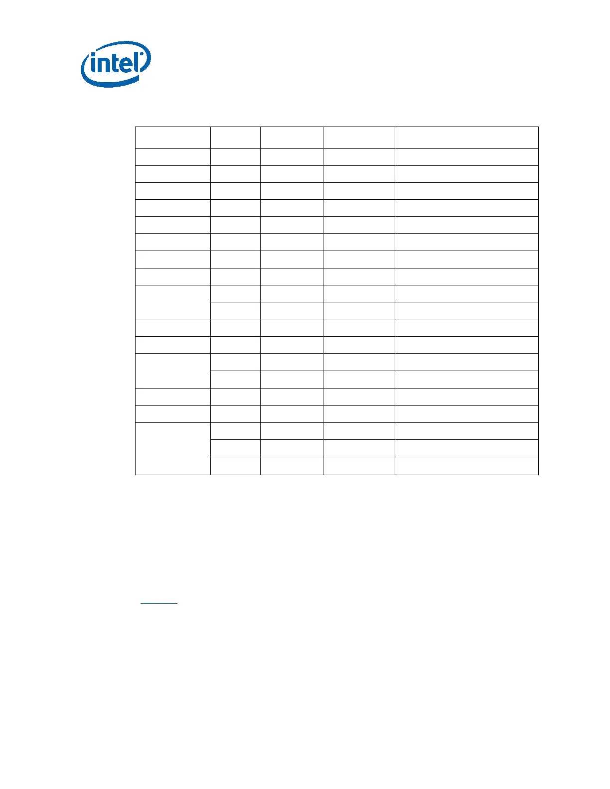
Table 9. Reworks for Different Port Mappings
Ports STUFF NO_STUFF Support
Slot 5 as x1 5 Xh
Slot 5 as x1;
LAN 6 Xf, Xg Xe, Re LAN;
Docking x1 7 Xb, Rb Xa, Ra Docking – x1 and
DMC 8 Xc Rc, Rd, Xd DMC – PCIe
5,6 Xh, Xe, Re Xf, Xg Slot 5 as x2, no LAN support;
Slot 5 as x2
Xb, Rb Xa, Ra Docking x1
Xc Rc, Rd, Xd DMC
5,6,7,8 Xh
Slot 5 as x4
Slot 5 as x4
Xe, Re Xf, Xg LAN - not supported
Xa Xb, Rb, Ra Docking - not supported
Xd, Rd Xc, Rc DMC - not supported
7 Xb, Ra Xa, Rb Docking – x1 not supported
Slot 6
Xh
Slot 5 as x1 –supported
Xf, Xg Xe, Re LAN – supported
Xc Rc, Rd, Xd DMC – supported
7, 8 Xb, Rb Xa, Ra Docking – x2 supported
Docking x2
Xd, Rc Xc, Rd DMC - not supported
Xf, Xg Xe, Re LAN supported
Xh
Slot 5 as x1 –supported
3.2.4 On-Board LAN
The development board supports 10/100/1000 Mbps Ethernet through the on-board
Intel 82579LM Gigabit Ethernet PHY (EU7M1). The LAN PHY has PCIe and SMBus
connections to the PCH. It is routed to Dock via the Docking Switch. Data transfer
occurs over PCIe lanes. Communication between the LAN controller and the LAN
Connected Device is handled via the SMBus whenever the system is in a low-power
state (Sx).
Figure 4
shows an on-board LAN block diagram.