Development Kit Features
2
nd
Generation Intel
®
Core™ Processor with Intel
®
6 Series Chipset Development Kit
March 2011 User Guide
Document Number: 325208-001 41
To simply read thermal information from the PCH by the external EC/fan controller,
only PCH SMBus signals (SML1_CLK and SML1_DATA) from the LPC sideband
connector can be used without connecting the EC on the LPC slot.
3.2.12 SPI
The Serial Peripheral Interface on the PCH can be used to support two compatible
flash devices (U8C2 and U8D2), storing Unified BIOS Code. Both U8C2 and U8D2 are
SOIC-8, 8 MB devices. An option is also provided for two SOIC-16 devices (U8C1 and
U8D1).
Of the SOIC-8 and SOIC-16 footprints supported, only one of these can be used at a
time. The footprints are positioned over one another. By default, U8C2 and U8D2 are
stuffed.
SPI sockets can be used. Socket KOZ is available, and a Dedi-Prog Header (J8E1) has
been provided for SPI programming.
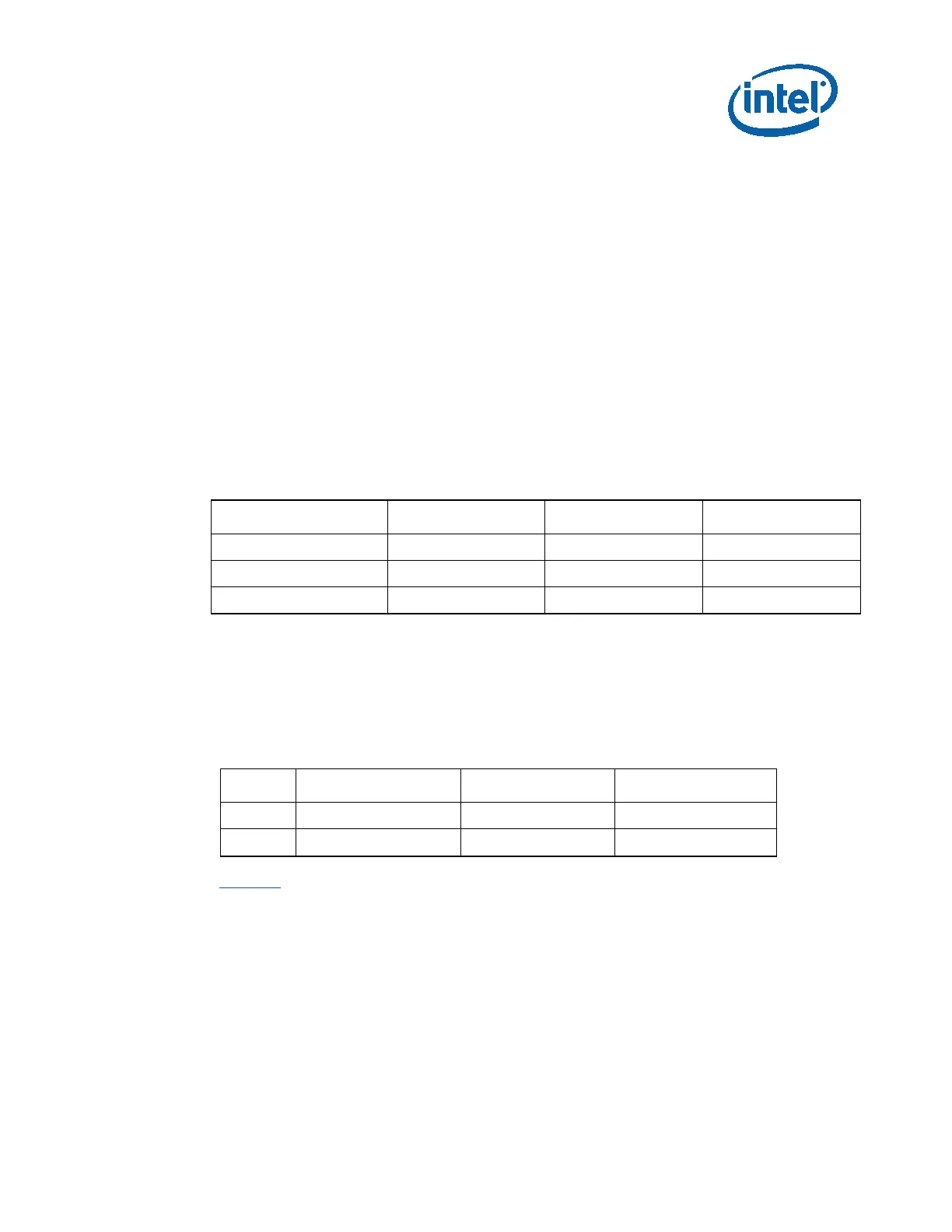
Table 14. Jumper Settings for SPI Programming
Mode J8C4 J8D1 J8C5
Normal Operation 1-X 1-X 1-X
Programming SPI0 1-2 1-2 1-2
Programming SPI1 1-2 2-3 1-2
3.2.12.1 Multi-BIOS Support
Multi-BIOS support is provided through an IO expander. Jumpers J9E1, J9E2, J9E3
need to be configured accordingly to select the required BIOS image.
The BIOS image is selected via the signals BIOS_SEL0, BIOS_SLE1, BIOS_SEL2. The
following table shows the jumper settings to set these signals to the required values.
Jumper J9E1 J9E2 J9E3
(1-2) BIOS_SEL0 = 0 BIOS_SEL1=0 BIOS_SEL2 =0
(1-x) BIOS_SEL0 = 1 BIOS_SEL1=1 BIOS_SEL2 =1
Table 15 shows the different images corresponding to the settings of BIOS_SEL2,
BIOS_SEL1, BIOS_SEL0, and the corresponding LEDs.