Development Board Summary
2
nd
Generation Intel
®
Core™ Processor with Intel
®
6 Series Chipset Development Kit
March 2011 User Guide
Document Number: 325208-001 53
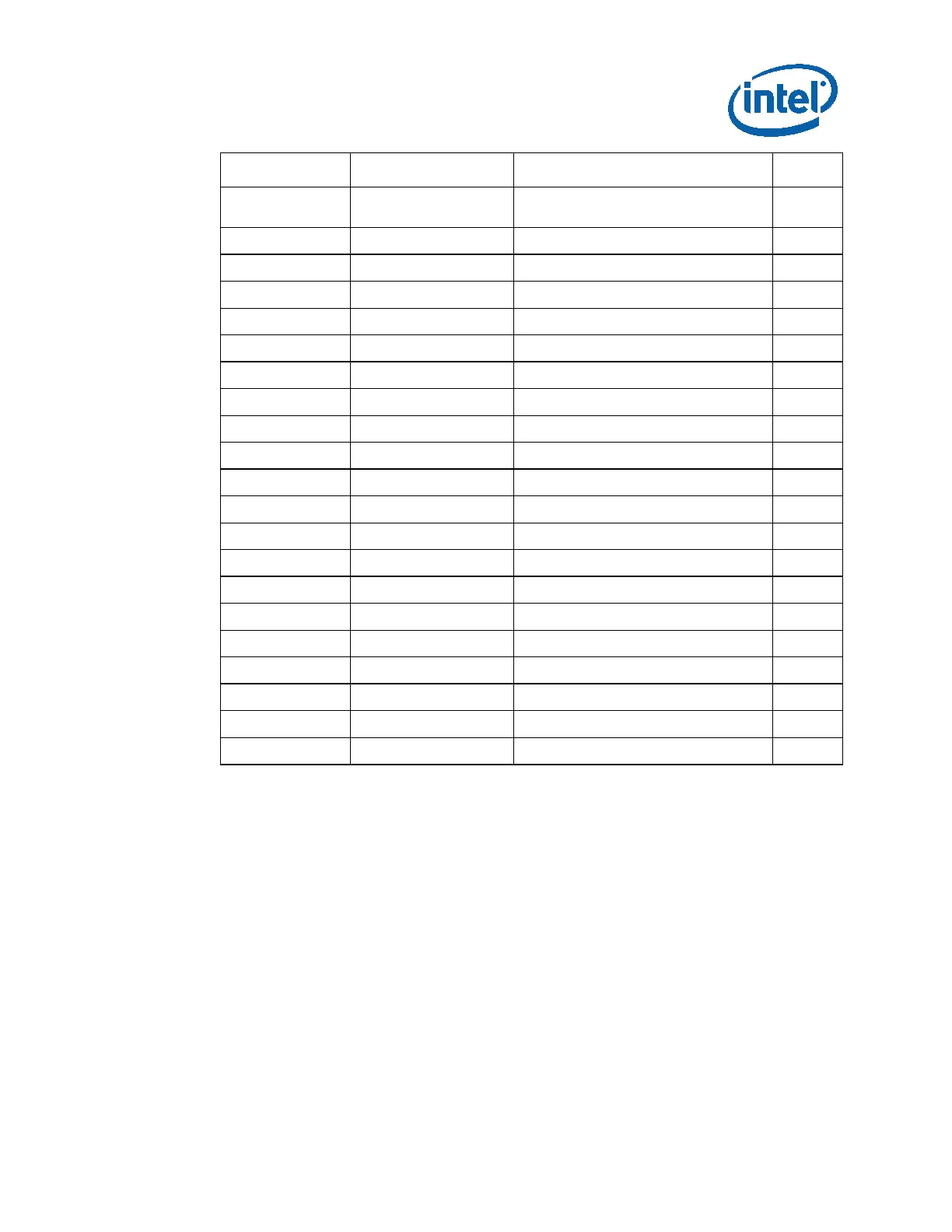
Reference Default Setting Comments PG
J9E10 (1-X)
RS232 PORT FOR EC FIRMWARE
DEBUG
49
J8C6 (1-2) IN CKT H8 PROGRAMMING 49
J8C7 (1-2) IN CKT H8 PROGRAMMING 49
J8G5 (1-2) H8 MODE SELECTION 50
J8G4 (1-X) H8 MODE SELECTION 50
J9F7 (1-X) SMC/KSC RST 50
J9F6 (1-X) THERM STRAP 50
J9F2 (1-X) KBC CORE DEBUG 50
J9E1 (1-X) BIOS SELECT 0 51
J9E2 (1-X) BIOS SELECT 1 51
J9E3 (1-X) BIOS SELECT 2 51
J9H1 (1-2) Vaux SELECT 51
J9H4 (1-X) SMC LID 51
J9H2 (1-X) VIRTUAL BATTERY 51
J9G1 (1-2) BOOT BLOCK PROGRAMING 52
J6G2 (1-2) VCCP VR 59
J5C5* (2-3) SA VR 61
J1B2 (1-X) IMVP7 VR ENABLE 64
J5G3 (1-X) G3 SUPPORT 70
J1E4 (1-X) FORCE POWER UP VBAT 70
J1F1 (1-X) FORCE SHUT DOWN 70
A jumper consists of two or more pins mounted on the motherboard. When a jumper
cap is placed over two pins, it is designated as 1-2. When there are more than two
pins on the jumper, the pins to be shorted are indicated as 1-2 (to short pin 1 to pin
2), or 2-3 (to short pin 2 to pin 3). When no jumper cap is to be placed on the
jumper, it is designated as 1-X.
4.4 Power On and Reset Button
The development board has two push-buttons, POWER and RESET. The POWER button
releases power to the entire board, causing the board to boot. The RESET button
forces all systems to warm reset. The two buttons are located near the processor. The
POWER button is located at SW1E1 (see #1 in table below) and the RESET button is
located at SW1E2 (see #2 in table below).