Development Kit Features
2
nd
Generation Intel
®
Core™ Processor with Intel
®
6 Series Chipset Development Kit
March 2011 User Guide
Document Number: 325208-001 35
HDMI
J3A1 is the on-board HDMI connector. HDMI connectors are also available on the
Eaglemont 2 Fab 3 AIC. Discrete level shifter is implemented for HDMI interface
support and the level translator IC on earlier boards has been removed.
Display Port (DP)
• DP connector (bottom port J5A1) is changed from earlier platforms to a stacked
dual USB and DP connector. The physical connector remains the same. Only its
placement has been changed on the development platform.
• The DP/USB2 is actually two connectors each placed on the board separately. The
middle and the top ports being part of a high-rise, dual-USB connector and the
bottom port used for the DP connector.
• Display Port connectors are also available on the Eaglemont 2 Fab 3 AIC.
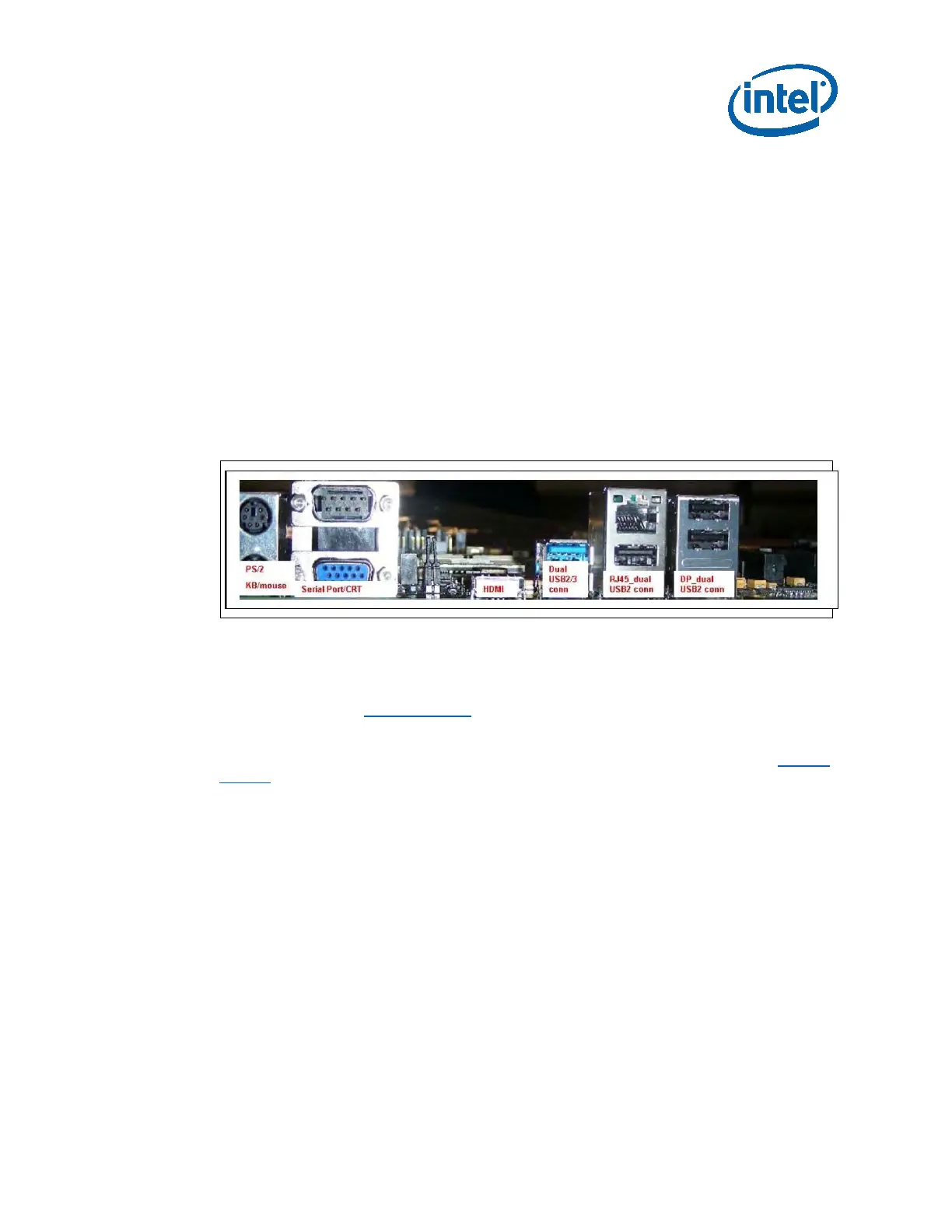
Figure 5. Back Panel Connectors
Embedded Display Port (eDP)
Port D on the Intel 6 Series chipset can be configured as eDP port. By default, eDP
from the processor is used, but optional support is provided for eDP from the PCH as
well. Please refer to Section 3.2.7.3
for more details.
If using eDP from the chipset, the LVDS cable has to has to be connected from the
development board to Elk Creek add-in card for the Sideband signals. Refer to Section
3.2.7.3 for details on enabling eDP from the chipset.
SDVO
• SDVO can be configured only on Port B. It is supported on ADD-2 add-in card,
which is inserted into the DDI slot J8C2.
• A maximum of two displays can be active at a time.
Digital Display Interface Configuration Modes
• 3x Display Ports
• 3x HDMI/DVI Ports
• 2x DP + 1x SDVO
• 2x DP + 1x HDMI/DVI
• 2x HDMI/DVI + 1x SDVO