Development Kit Features
2
nd
Generation Intel
®
Core™ Processor with Intel
®
6 Series Chipset Development Kit
March 2011 User Guide
Document Number: 325208-001 37
3.2.7.2 DMC Support
The development board supports a Display Mini PCIe connector. The three primary
data interfaces defined for PCIe Mini Card are: PCIe, USB and DisplayPort.
On the board,
• PCIe port 8 is connected by default to DMC;
• An option is provided for Display Port D to be connected to DMC. The reworks
required on the board are:
o UNSTUFF C5A3, C5A4, C5A5, C5A6, C5B3, C5B4, C5B1, C5B2, C5B5,
C5B7
o STUFF C5N3, C5N4, C5M4, C5M5, C5N1, C5N2, C5M2, C5M3, C5B6, C5B8
with 0.1 µF cap
o The caps unstuffed as shown in UNSTUFF above can be used for those
shown in STUFF, also above
o For HPD, UNSTUFF R4A2 and stuff R4A3 with 0 Ohm
An option is provided for USB2.0 port 0 to be connected to DMC. For this, the
following reworks have to be done: STUFF R5B12, R5B13, R6A11, R6A12 (with 0
Ohms), UNSTUFF R5B11, R5B14.
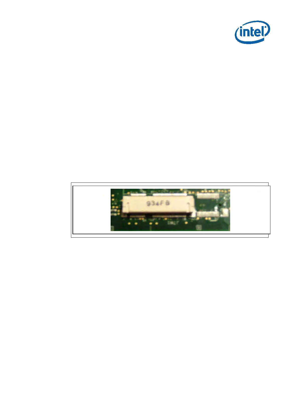
Figure 7 Mini PCIe Connector Soldered In Place of DMC
• C-link support is also provided for DMC. The reworks required for this are:
o UNSTUFF R7C29, R7D1, R7C26
o STUFF R7C25, R7C24, R7C23 (with 0 Ohms)
3.2.7.3 Switchable Graphics
“Switchable graphics” is a platform feature where you can seamlessly switch between
internal and external graphics modes.
This feature is supported on the 2nd Generation Intel
®
Core™ processor family and
Intel
®
6 Series Chipset development board via the Elk Creek-4 add-in card (on PEG
slot).
To enable switchable graphics, the J9F4 setting needs to be changed to (2-3). No
board reworks are required.
All display interfaces are from the PCH other than eDP, which is supported via the 2nd
Generation Intel
®
Core™ processor family. If one of the DP ports from PCH is to be