4.4. Monitor On-Board Power Regulator through Power Monitor GUI
The Power Monitor GUI reports most power rails’ voltage, current, and power
information on the board. It also collects temperature from FPGA die, power modules,
and diodes assembled on PCB.
The Power Monitor GUI communicates with the system MAX 10 through a 10-pin JTAG
header (J11) or USB port (J10). System MAX 10 monitors and controls power
regulator, temperature/voltage/current sensing chips through a 2-wire I
2
C bus.
The instructions to run Power Monitor GUI are stated in the Running the BTS GUI on
page 16. Alternatively, you can start using the Power Monitor feature by selecting the
Power icon on the BTS GUI.
Note: You cannot run the stand-alone Power Monitor GUI when the BTS or the Clock
Controller GUI is running at the same time.
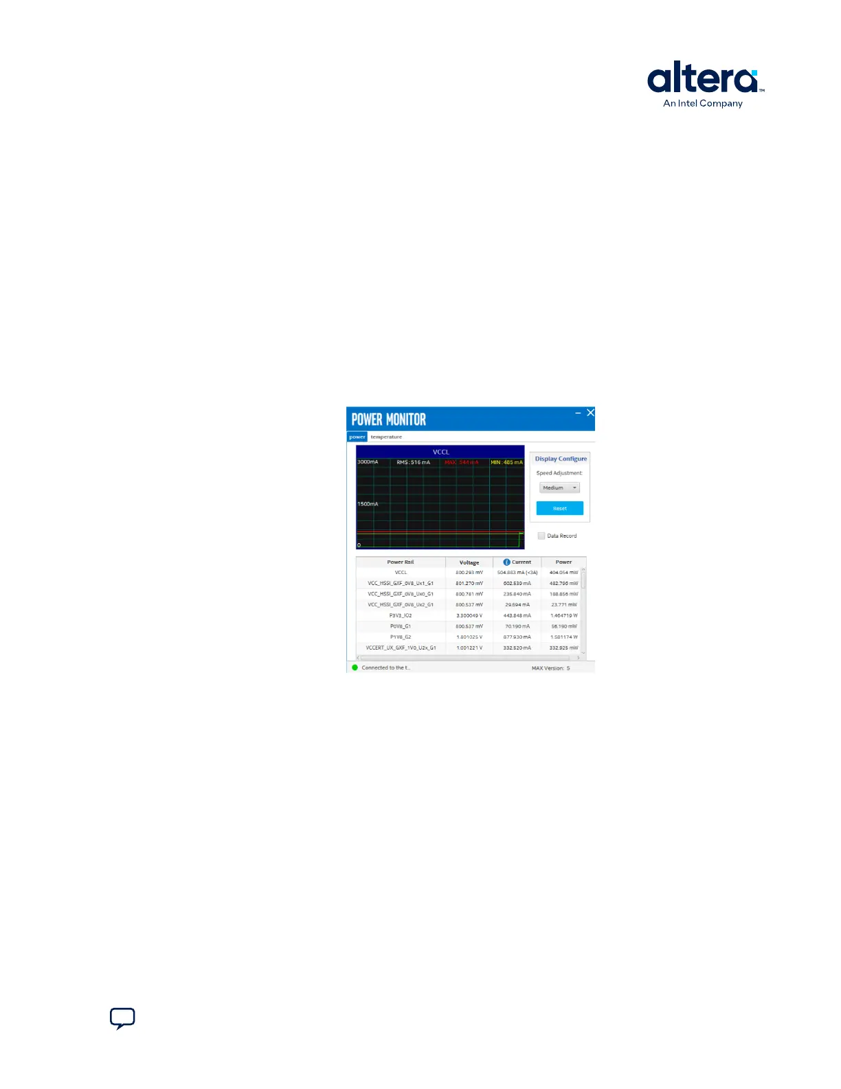
Figure 28. Power Monitor GUI—The Power Tab
The following sections describe the details of the Power Monitor GUI.
Display Configure
• Speed Adjustment: Adjusts the update rate of the current curve.
• Reset: Regenerates the graph.
Data Record
When the box is checked, the telemetry data of the selected power rail can be
recorded. It saves the data into a .csv file in the log directory.
4. Board Test System
776646 | 2024.11.21
Send Feedback
Agilex
™
7 FPGA I-Series Transceiver (6 × F-Tile) Development Kit User Guide
37