4.3. Control On-Board Clock through Clock Controller GUI
The Clock Controller GUI can change the on-board Si5391/Si5395-1/Si5395-2/Si5518.
The instructions to run Clock Controller GUI are stated in the Running the BTS GUI on
page 16. Alternatively, you can start using the Clock Controller feature by selecting
the Clock icon on the BTS GUI.
The Clock Controller communicates with the system MAX 10 device through a 10-pin
JTAG header J11 or USB port J10. Then, system MAX 10 controls these programmable
clock parts through a 2-wire I
2
C bus.
Note: You cannot run the stand-alone Clock Controller GUI application when the BTS or
Power Monitor GUI is running at the same time. Si5518 can be controlled only when a
design in which the SPI interface is instantiated, such as the bts_config.sof under
the board_test_system\image\ES folder has been downloaded to the FPGA.
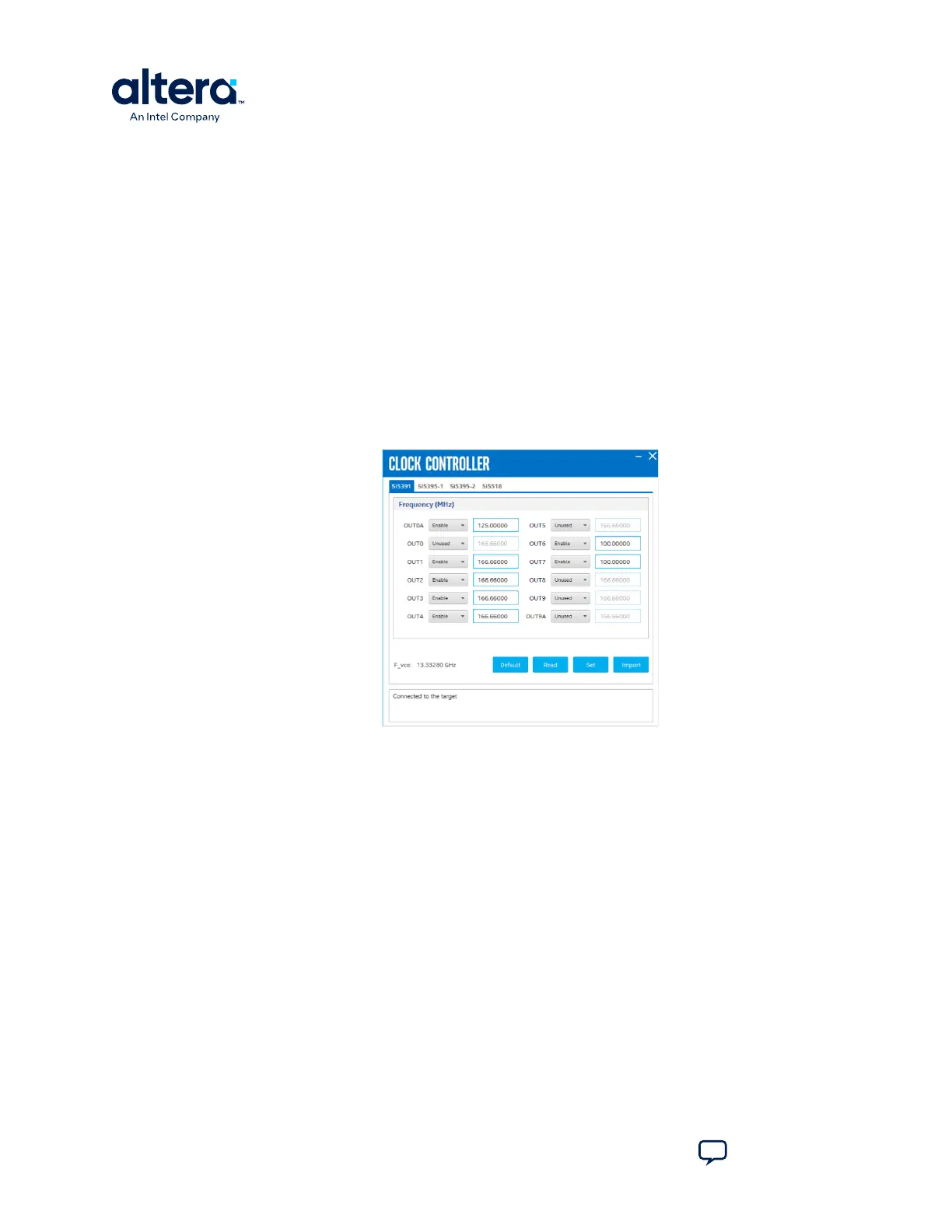
Figure 24. Si5391
The following sections describe the Clock Controller buttons.
Read
Reads the current frequency setting for the oscillator associated with the active tab.
Default
Sets the frequency for the oscillator associated with the active tab back to its default
value. This can also be accomplished by power cycling the board.
Set
Sets the programmable oscillator frequency for the selected clock to the value in the
OUTx output controls for Si5391. Frequency changes might take several milliseconds
to take effect. You might see glitches on the clock during this time. Altera
recommends resetting the FPGA logic after changing frequencies.
4. Board Test System
776646 | 2024.11.21
Agilex
™
7 FPGA I-Series Transceiver (6 × F-Tile) Development Kit User Guide
Send Feedback
34