EasyManua.ls Logo

Intel Intel® Core i7 User Manual

Intel Intel® Core i7
73 pages
To Next Page IconTo Next Page
To Previous Page IconTo Previous Page
Page #30 background image
30 323094 Dev Kit Manual
Table 8. PCI Express* Ports
PCI-E* Port
Default Destination
Optional Destination
1
PCI-E Slot 1 (J6C2)
-
2
PCI-E Slot 2 (J6D2)
(in-line with Slot 1)
-
3
PCI-E Slot 3 (J7C1)
-
4
PCI-E Slot 4 (J7D2)
-
5
PCI-E Slot 5 (J6C1)
-
6
LAN (EU7M1)
-
7
DOCKING (J9C2)
PCIe SLOT6 (J8C1)
8
DOCKING (J9C2)
-
3.7.2.2 PCI Slots
The development kit does not have any PCI slots on the motherboard. Three 5V PCI slots are
supported via PCI Extension Card.
3.7.2.2.1 PCI Gold-Fingers
A gold-finger connector (S9B1) is also supplied on the motherboard, which allows an external
PCI expansion board to connect to motherboard. The PCI expansion board has three
additional PCI slots allowing the user greater expansion. See section Daughter and Plug-in
Cards for more information on the PCI expansion board add-in card.
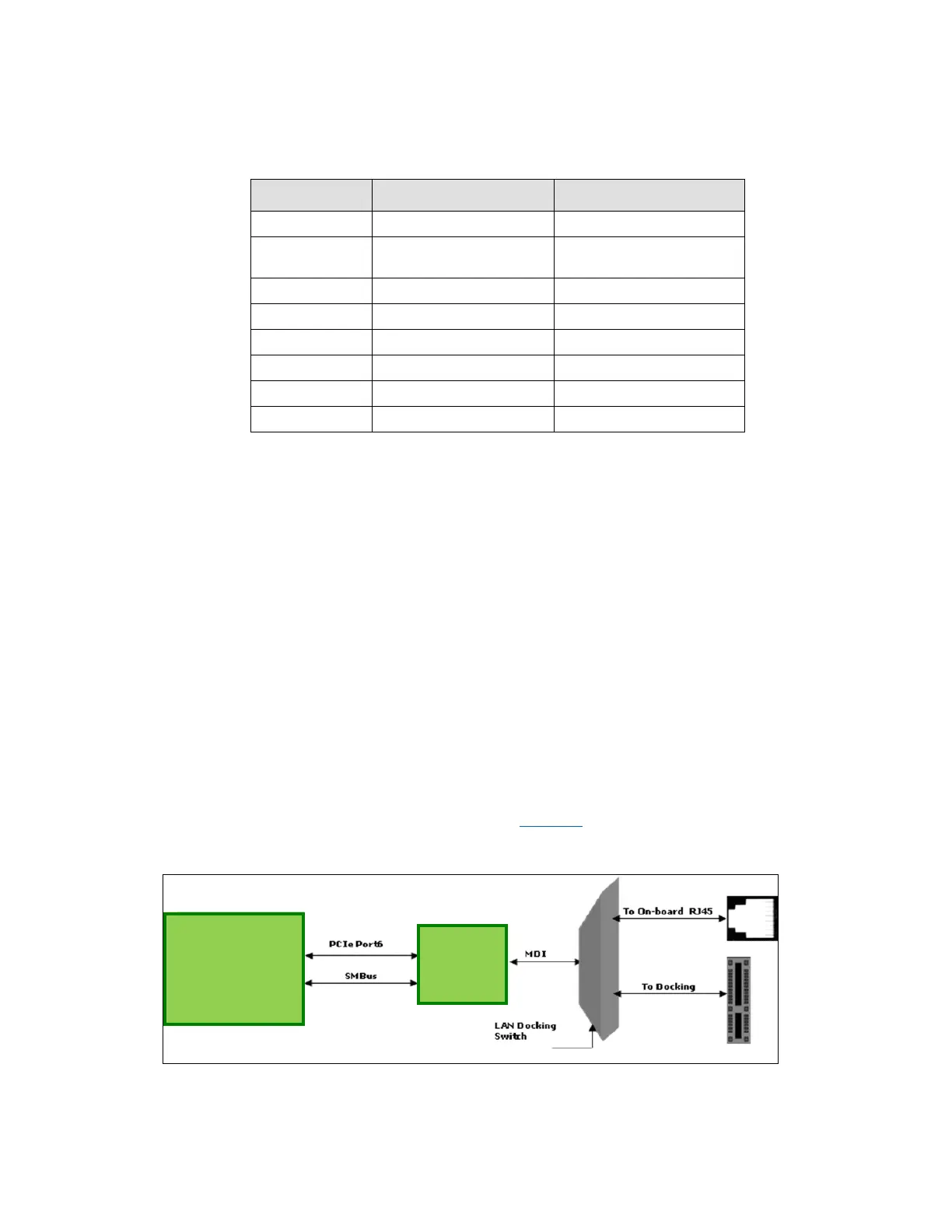
3.7.2.3 On-Board LAN
The development kit supports 10/100/1000 Mbps Ethernet on board via the Intel
®
82577 GbE
PHY. It has a PCI-E and SM-BUS link to the Chipset. Data Transfer happens over PCI-E lanes.
Communication between the LAN Controller and the LAN Connected Device is done through
SMBus whenever the system is in a low power state (Sx). LAN is also supported over
DOCKING.
A block Diagram of the implementation is given in Figure 3.
Figure 3. Block Diagram of On-board LAN Implementations
Intel
®
QM57
Express
Chipset
GbE LAN
Card

Table of Contents

Question and Answer IconNeed help?

Do you have a question about the Intel Intel® Core i7 and is the answer not in the manual?

Intel Intel® Core i7 Specifications

General IconGeneral
BrandIntel
ModelIntel® Core i7
CategoryComputer Hardware
LanguageEnglish

Summary

About This Manual

Content Overview

Details the manual's sections, including setup, features, and support.

Text Conventions

Explains notation, symbols, and abbreviations used in the document.

Glossary of Terms and Acronyms

Defines technical terms and acronyms relevant to the development kit.

Related Documents

Lists other publicly available documents related to the development kit.

Development Kit Technical Support

Information on obtaining technical assistance and support for the development kit.

Getting Started

Development Kit Contents

Lists all hardware, software, and documentation included in the development kit.

Required Hardware Not Included

Lists additional hardware necessary for setting up and operating the system.

Required Software Not Included

Lists additional software necessary for operating the system.

Workspace Preparation

Guidelines for preparing the workspace and safety precautions for handling the development board.

System Setup

Step-by-step instructions for setting up and connecting the development kit system.

System Power-Up

Procedures for powering up the development kit and entering the BIOS setup.

System Power-Down

Describes the three options for powering down the development kit system.

System BIOS

Covers BIOS configuration, programming via USB, and flashing via SPI.

Development Board Features

Block Diagram

Provides a high-level system block diagram of the development kit.

Mechanical Form Factor

Describes the form factor of the development kit board.

Development Board Features Table

Summarizes the key features of the development kit in a table format.

Driver Key Features

Highlights key features of the drivers included with the development kit.

BIOS Key Features

Details the features and capabilities of the pre-installed AMI BIOS.

System Thermal Management

Explains the importance of thermal management and the provided thermal solution.

System Features and Operation

Details system features and operation, covering processor and chipset aspects.

Development Board Physical Hardware Reference

Primary Features

Describes major components and their locations on the motherboard, top and bottom views.

Connectors

Details all connectors on the motherboard and back panel, including their pinouts.

Configuration Settings

Explains jumper and switch settings for configuring the development board.

Daughter and Plug-in Cards

PCIe Add-in Card

Information on the PCIe add-in card for enabling 2x8 PCIe Bifurcation.

PCI Expansion Card

Details the PCI Expansion card with three PCI slots and additional connectors.

Port 80-83 Add-in Card

Describes the Port 80-83 add-in card for BIOS POST code display and LPC interfaces.

Heatsink Installation Instructions

Disassembling Fan/Heatsink Assembly

Steps to disassemble the fan/heatsink assembly into its primary components.

Installing Fan/Heatsink

Detailed instructions for installing the fan/heatsink assembly onto the processor.

Related product manuals