Dev Kit Manual 51 323094
1-2: Enable Gfx VID
Override
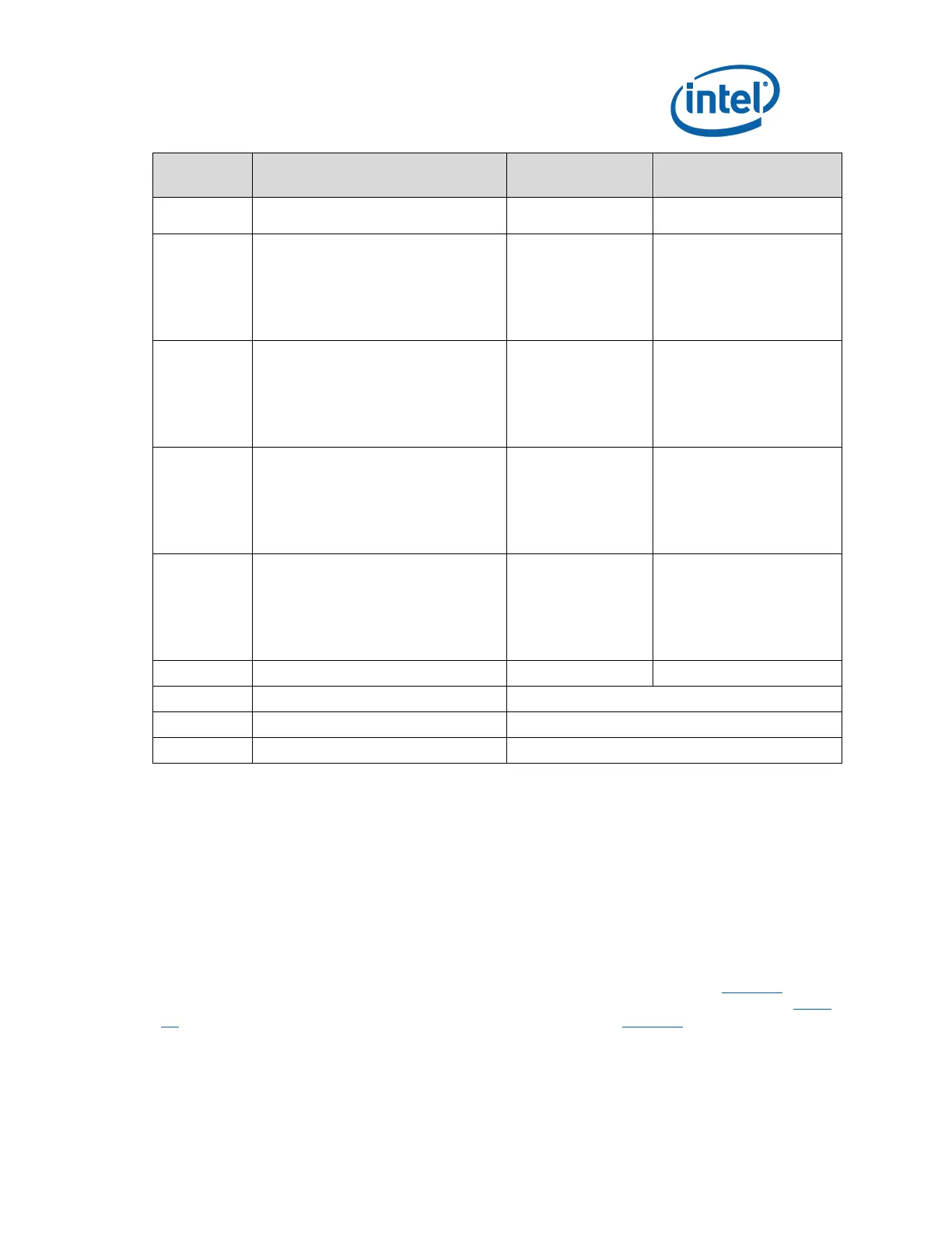
USB Header 1 – Port 4 and Port 5 –
PCIe Slot 1 and Slot 2
1-3: USBP4N connected
2-4: USBP5N connected
5-7: USBP4P grounded
6-8: USBP5P grounded
9-10: no connect
USB Header 2 – Port 6 and Port 7 –
PCIe Slot 3 and Slot 4
1-3: USBP6N connected
2-4: USBP7N connected
5-7: USBP6P grounded
6-8: USBP7P grounded
9-10: no connect
USB Header 3 – Port 10 and Port 11
1-3: USBP10N connected
2-4: USBP11N connected
5-7: USBP10P grounded
6-8: USBP11P grounded
9-10: no connect
USB Header 4 – Port 12 and Port 13
1-3: USBP12N connected
2-4: USBP13N connected
5-7: USBP12P grounded
6-8: USBP13P grounded
9-10: no connect
Flash Descriptor Security Override
Note: A jumper consists of two or more pins mounted on the motherboard. When a jumper cap is
placed over two pins, it is designated as IN or 1-2. When there are more than two pins on the
jumper, the pins to be shorted are indicated as 1-2 (to short pin 1 to pin 2), or 2-3 (to short
pin 2 to pin 3), etc. When no jumper cap is to be placed on the jumper, it is designated as
OUT or 1-X.
4.4 Power On and Reset Push Buttons
The motherboard has two push-buttons, POWER and RESET. The POWER button releases
power to the entire board causing the board to boot. The RESET button forces all systems to
warm reset. The two buttons are located near the Processor (Marked as #3 in Table 20) close
to the East edge of the board. The POWER button is located at SW1E1 (Marked as #1 in Table
20) and the RESET button is located at SW1E2 (Marked as #2 in Table 20).