EasyManua.ls Logo

Intel Intel® Core i7 User Manual

Intel Intel® Core i7
73 pages
To Next Page IconTo Next Page
To Previous Page IconTo Previous Page
Page #63 background image
Dev Kit Manual 63 323094
5 Daughter and Plug-in Cards
5.1 PCIe* Add-in Card
The PCIe* add-in card can be used to enable 2 x 8 PCIe* Bifurcation.
Note: The eDP on the PCIe add-in card will not work with the processor because of specification
change and lane reversal. The PCI graphics card needs to be used to enable eDP.
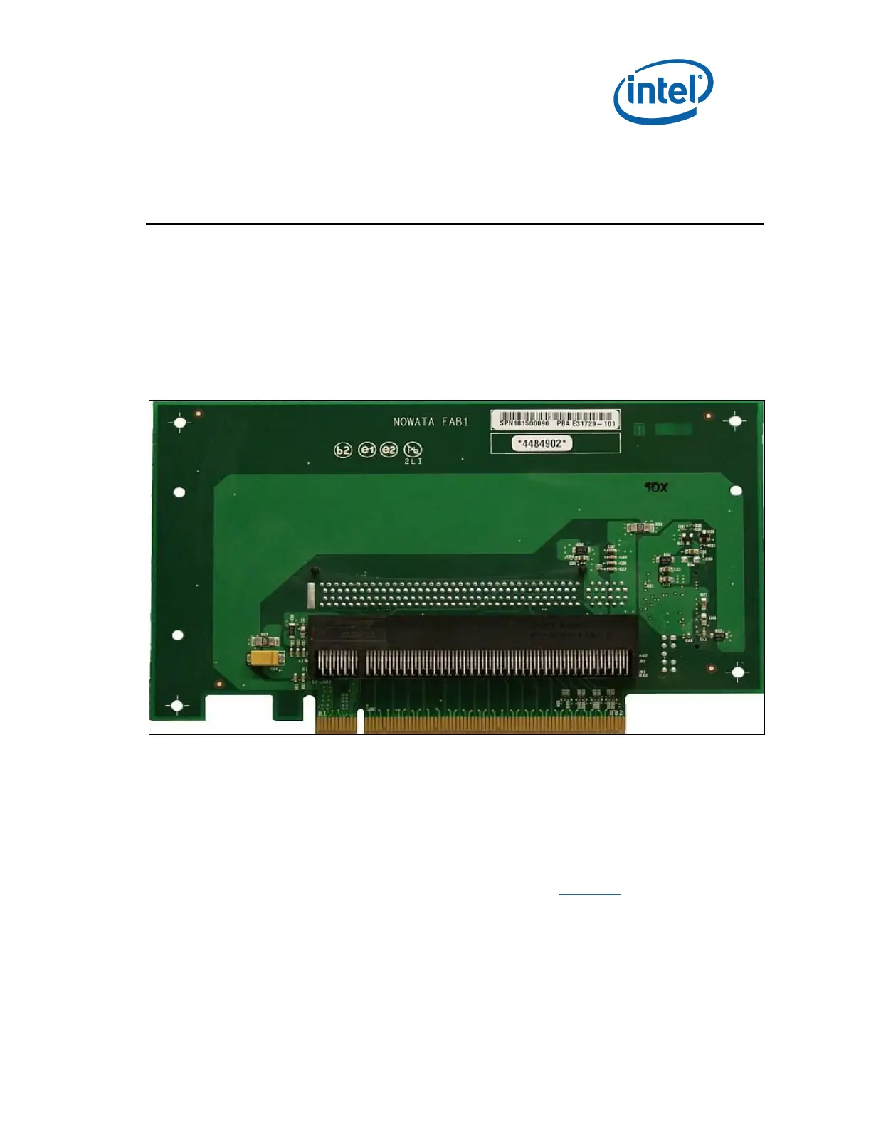
Figure 10. PCIe* Add-in Card
5.2 PCI Expansion Card
The PCI Expansion card is provided to offer three PCI slots and one Goldfinger PCI slot on the
evaluation board. The PCI Expansion card also contains a floppy disk drive connector, parallel
port connector, and a serial port connector. To connect PCI Expansion card slide the
horizontal PCI connector on PCI Expansion card onto the gold-fingers on the evaluation board.
To connect the LPC bus to enable the floppy disk drive connector, parallel port connector, and
a serial port connector, connect the ribbon cable as depicted in Figure 11. CLKRUN protocol is
supported on PCI Expansion card board for only those PCI cards which support CLKRUN#; else
CLKRUN# should be disabled in BIOS.
Upon boot up, the system BIOS on the evaluation board automatically detects that PCI
Expansion card is present and connected to the system. The system BIOS then performs all
needed initialization to fully configure PCI Expansion card. For additional information see the

Table of Contents

Question and Answer IconNeed help?

Do you have a question about the Intel Intel® Core i7 and is the answer not in the manual?

Intel Intel® Core i7 Specifications

General IconGeneral
BrandIntel
ModelIntel® Core i7
CategoryComputer Hardware
LanguageEnglish

Summary

About This Manual

Content Overview

Details the manual's sections, including setup, features, and support.

Text Conventions

Explains notation, symbols, and abbreviations used in the document.

Glossary of Terms and Acronyms

Defines technical terms and acronyms relevant to the development kit.

Related Documents

Lists other publicly available documents related to the development kit.

Development Kit Technical Support

Information on obtaining technical assistance and support for the development kit.

Getting Started

Development Kit Contents

Lists all hardware, software, and documentation included in the development kit.

Required Hardware Not Included

Lists additional hardware necessary for setting up and operating the system.

Required Software Not Included

Lists additional software necessary for operating the system.

Workspace Preparation

Guidelines for preparing the workspace and safety precautions for handling the development board.

System Setup

Step-by-step instructions for setting up and connecting the development kit system.

System Power-Up

Procedures for powering up the development kit and entering the BIOS setup.

System Power-Down

Describes the three options for powering down the development kit system.

System BIOS

Covers BIOS configuration, programming via USB, and flashing via SPI.

Development Board Features

Block Diagram

Provides a high-level system block diagram of the development kit.

Mechanical Form Factor

Describes the form factor of the development kit board.

Development Board Features Table

Summarizes the key features of the development kit in a table format.

Driver Key Features

Highlights key features of the drivers included with the development kit.

BIOS Key Features

Details the features and capabilities of the pre-installed AMI BIOS.

System Thermal Management

Explains the importance of thermal management and the provided thermal solution.

System Features and Operation

Details system features and operation, covering processor and chipset aspects.

Development Board Physical Hardware Reference

Primary Features

Describes major components and their locations on the motherboard, top and bottom views.

Connectors

Details all connectors on the motherboard and back panel, including their pinouts.

Configuration Settings

Explains jumper and switch settings for configuring the development board.

Daughter and Plug-in Cards

PCIe Add-in Card

Information on the PCIe add-in card for enabling 2x8 PCIe Bifurcation.

PCI Expansion Card

Details the PCI Expansion card with three PCI slots and additional connectors.

Port 80-83 Add-in Card

Describes the Port 80-83 add-in card for BIOS POST code display and LPC interfaces.

Heatsink Installation Instructions

Disassembling Fan/Heatsink Assembly

Steps to disassemble the fan/heatsink assembly into its primary components.

Installing Fan/Heatsink

Detailed instructions for installing the fan/heatsink assembly onto the processor.

Related product manuals