Dev Kit Manual 39 323094
power measurement resistors are 2mOhm by default. Power on a particular subsystem is
calculated using the following formula:
R = value of the sense resistor (typically 0.002Ω)
V = the voltage difference measured across the sense resistor.
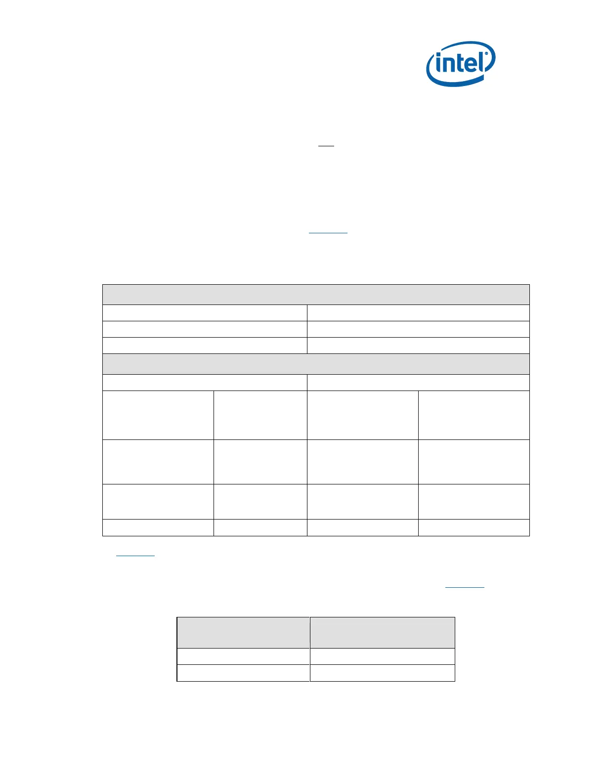
It is recommended that the user use a high precision digital multimeter tool such as the
Agilent* 34401A digital multi-meter. Refer to Table 14 for a comparison of a high precision
digital multi-meter (Agilent 34401A) versus a standard precision digital multimeter (Fluke*
79).
Table 14. Digital Multimeter
Voltage Difference Across Resistor:
Agilent 34401A (6 ½ digit display)
Fluke 79 (3 digit display)
(±0.0030% of
reading)
+ (±0.0030% of
range)
Min Voltage Displayed:
Calculated Power:
Min Voltage Displayed:
Calculated Power:
Max Voltage Displayed:
Calculated Power:
Max Voltage Displayed:
Calculated Power:
As Table 14 shows the precision achieved by using a high precision digital multimeter versus a
standard digital multimeter is ~33 times more accurate.
The Power Measurement resistors provided for the various rails are listed in Table 15:
Table 15. Power Measurement Resistor for Power Rails
REFDES of the
Power Measurement Resistor